3-M3
M8540, M9540, WSM
TRANSMISSION
2. POWER TRAIN FOR TRAVELING GEAR
[1] SHUTTLE SHIFT SECTION
(1) Structure
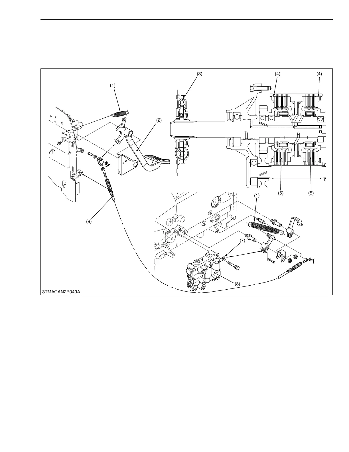
The damper disc (3) helps ease the shock load when engaging the shuttle clutch.
The belleville washer (cupped spring washer) (4) helps ease the engaging shock together with modulating valve
effect.
The hydraulic shuttle clutch, which switches forward and reverse running, function as the traveling clutch. When
the clutch pedal (2) is depressed, the clutch spool of shuttle valve (8) moves via the clutch cable (9).
As for the oil, it does not flow to both the forward side (5) and reverse side (6) of the clutch pack, the clutch pack
enters the state of “Disengaged” and power is not transmitted.
(1) Return Spring
(2) Clutch Pedal
(3) Damper Disc
(4) Belleville Washer
(Cupped Spring Washer)
(5) Forward Side Clutch
(6) Reverse Side Clutch
(7) Clutch Spool
(8) Hydraulic Shuttle Valve
(9) Clutch Cable

 Loading...