9-S35
M8540, M9540, WSM
ELECTRICAL SYSTEM
(2) Lever Combination Switch and Horn Switch (CABIN Model)
Checking Connector Voltage
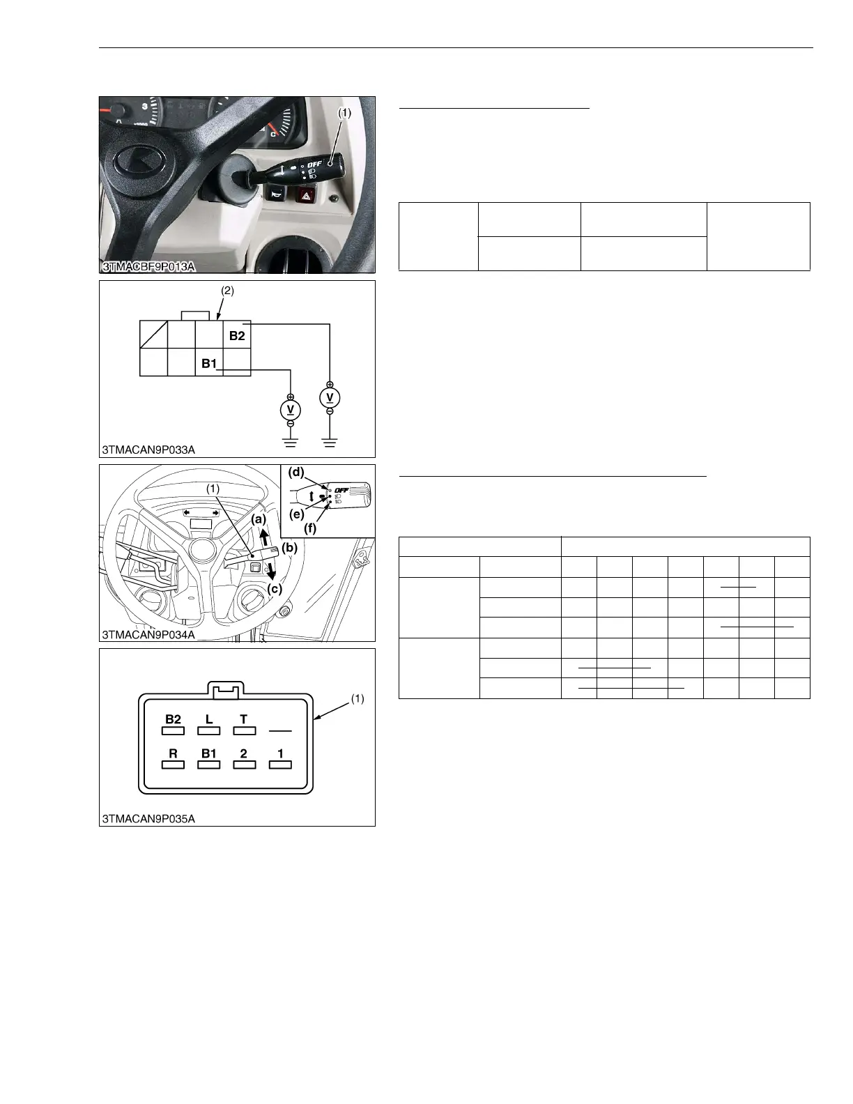
1. Disconnect the lever combination switch connector (1).
2. measure the voltage with voltmeter across the connector
terminal B1 and chassis, across the terminal B2 and chassis.
3. if the voltage differs from the battery voltage, the wiring harness,
fuses or main switch is faulty.
W1100674
Checking Light Switch and Turn Signal Switch
1. Test the continuity through the switch with an ohmmeter.
2. If the continuity specified below is not indicated, the switch is
faulty.
W1032505
Voltage
Main switch at
“OFF”
Terminal B1 –
Chassis
Approx. battery
voltage
Main switch at
“ON”
Terminal B2 –
Chassis
(1) Lever Combination Switch (2) Combination Switch Connector
(Wire Harness Side)
Terminal
Continuity Position B1 T 1 2 B2 R L
Turn signal
switch
R.H. (a) OO
OFF (b)
L.H. (c) OO
Light switch
OFF (d)
Lo (e) OOO
Hi (f) OO O
(1) Lever Combination Switch
Connector (Switch Side)
(a) Right Turn
(b) OFF
(c) Left Turn
(d) OFF
(e) Head Light (Lo)
(f) Head Light (Hi)

 Loading...