Vehicle Super Probe
- 10 -
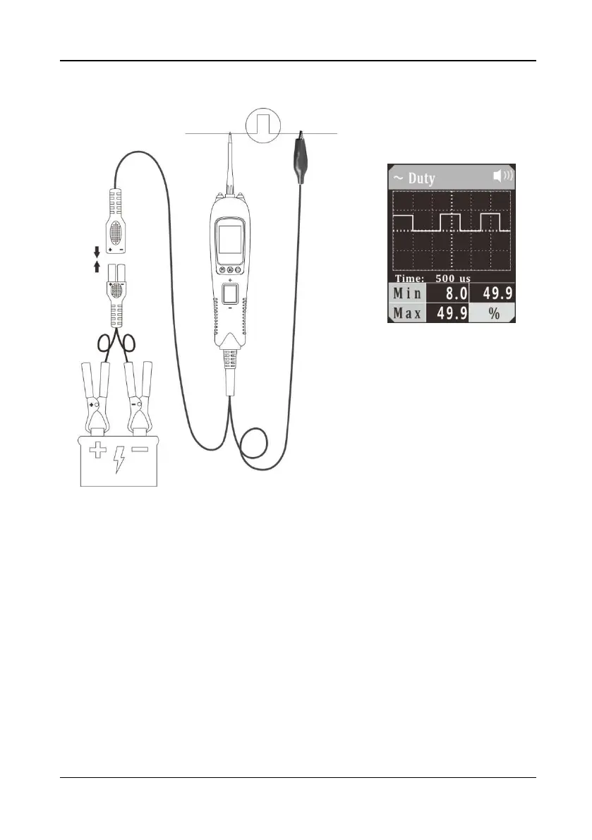
5.4 Duty Cycle
Figure 6
1)
Clip the red alligator clip to the battery positive pole; Clip the black alligator clip to
the battery negative pole.
2) Once the device is powered on, it will enter DC voltage test mode as default.
Short press the mode button to enter the menu, short press the down button to
place the cursor in the Duty Cycle mode, and short press the mode button to
enter the Duty Cycle waveform display mode.
3) The auxiliary ground wire is connected to the common end of the circuit under test,
and the probe contacts the test circuit. The LCD display will show the minimum
duty cycle, maximum duty cycle and waveform duty cycle (Figure 6), and display
the signal waveform in real time. You can adjust the sampling frequency by
pressing the Up/Down Button. In Figure 6, “time: 500us” is the time interval
indicated by each large grid. This time reading will change with the sampling
frequency.
4) Long press and hold the mode button until the device switches to digital display
mode. The LCD display will display the current duty cycle, minimum duty cycle,
and maximum duty cycle.