Vehicle Super Probe
- 15 -
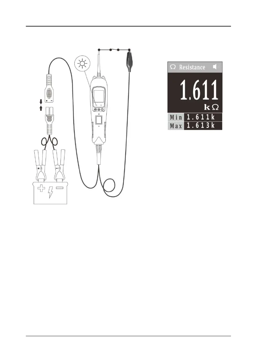
5.9 Continuity Testing
Figure 12
1)
Clip the red alligator clip to the battery positive pole; Clip the black alligator clip to
the battery negative pole.
2) Once the device is powered on, it will enter DC voltage test mode as default.
Short press the mode button to enter the menu, short press the down button to
place the cursor in the Resistance mode, and short press the mode button to
enter the Resistance mode.
3) Using the probe tip and the auxiliary ground lead, it can test continuity of wires
and components connected or disconnected with the vehicle’s electrical system.
When the probe tip is contacting a good ground, the LCD will show 0Ω and green
LED will be on. A beep tone will sound .
4) In other cases, the LCD shows the resistance of the component under test, along
with the maximum and minimum values during the measurement, as shown in
Figure 12.
5) If the resistance value is greater than 1000KΩ, the LCD will show “0L”.
6) Note: You can use the probe tip to pierce the plastic insulation on a wire. This
means that you can test the circuit without disconnecting anything.