Vehicle Super Probe
- 16 -
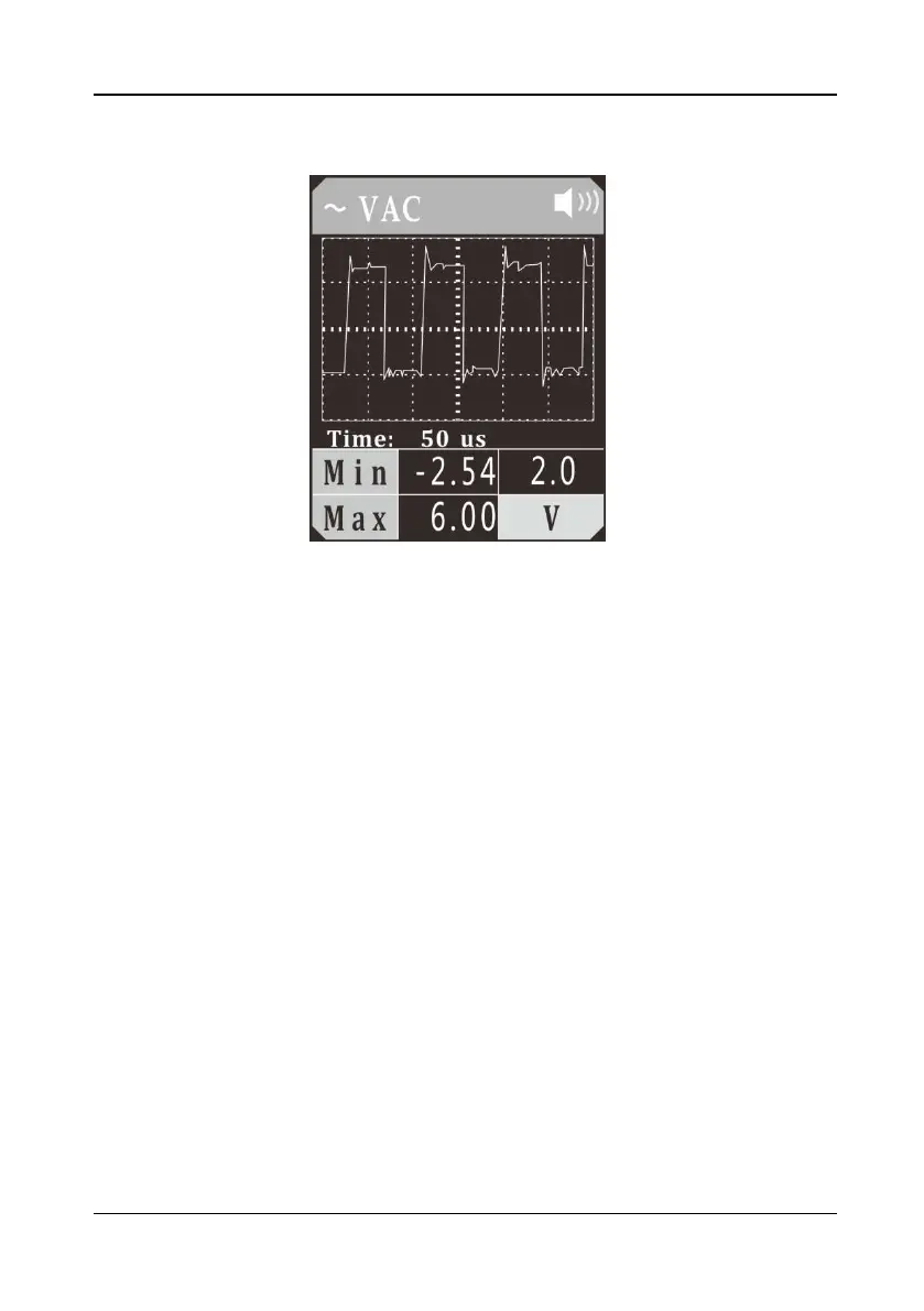
5.10 Signal Circuit Testing
Figure 13
Once you extract a DTC from the vehicle and realize that troubleshooting begins with
some kind of sensor circuit, there is a quick test you can perform to verify the code.
Testing your sensor is easy while using the tool.
For example, if you suspect there is a problem with your M.A.P. sensor circuit, then
you may follow the procedure involved to test this sensor:
1) Set the tool in AC Voltage mode, using the probe tip (with chassis ground) or the
auxiliary ground lead.
2) Connect vacuum pump to MAP sensor.
3) Contact the probe tip to the MAP sensor positive terminal and observe the LCD
readings which should be a sine wave in normal condition.
4) Apply vacuum.
5) Release vacuum and observe the LCD readings. (Figure 13)
6) If the LCD readings are abnormal, there is a problem with this sensor.