Vehicle Super Probe
- 14 -
3) Contact the probe tip to diode positive terminal, connect the auxiliary ground lead
to diode negative terminal, the screen will display the forward voltage drop, which
indicates forward bias. If swapping the probe tip with auxiliary ground lead, the
screen will not display voltage, which indicates reverse bias. It also displays the
maximum and minimum values during measurement, as shown in (Figure 9).
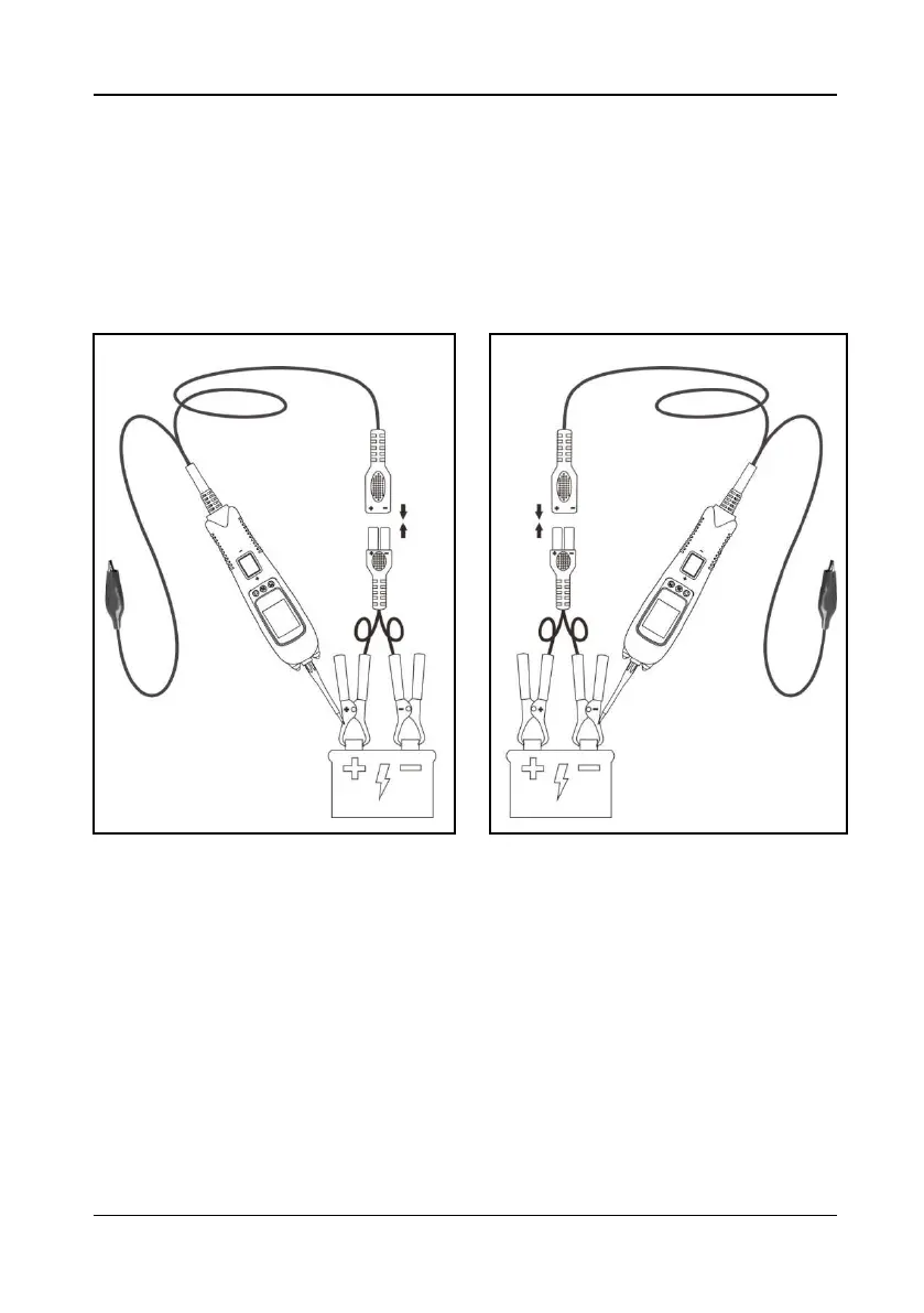
5.8 Voltage & Polarity Testing
Figure 10 Figure 11
1) Clip the red alligator clip to the battery positive pole; Clip the black alligator clip to
the battery negative pole.
2) Contact the probe tip to the circuit under test.
3) If contact the probe tip to a POSITIVE circuit (Figure 10), the red LED will light
and the LCD displays the voltage with a highest resolution of 0.01V. A beep tone
will sound. If contact the probe tip to a NEGATIVE circuit (Figure 11), the green
LED will light and the LCD displays the voltage with a highest resolution of 0.01V.
A beep tone will sound. If contact the probe tip to an OPEN circuit, neither of the
LED will light.