Vehicle Super Probe
- 13 -
place the cursor in the Resistance mode, and short press the mode button to
enter the Resistance mode.
3) The probe contacts one end of the measured resistance, and the auxiliary ground
lead is connected to the other end of the measured resistance. The LCD display
will read the resistance between the tip and auxiliary ground lead. (Figure 8)
4) When resistance value is less than 30Ω, the instrument buzzer will alarm and the
green LED will light. This function can be used as continuity test.
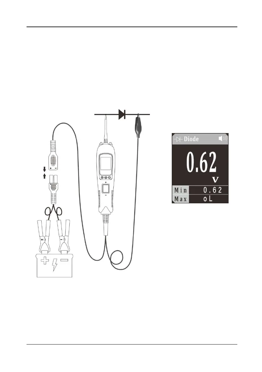
5.7 Diode
Figure 9
1) Clip the red alligator clip to the battery positive pole; Clip the black alligator clip to
the battery negative pole.
2) Once the device is powered on, it will enter DC voltage test mode as default.
Short press the mode button to enter the menu, short press the down button to
place the cursor in the Diode mode, and short press the mode button to enter the
Diode mode.