Vehicle Super Probe
- 5 -
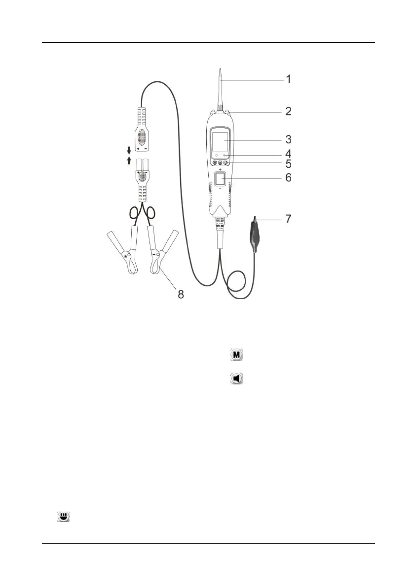
4. Product Appearance
Figure 1
1) Probe Tip - Contacts the circuit or
component to be tested.
2) LED Lights - Illuminates dark work
areas or work areas at night.
3) LCD Display - Indicates test results,
test data and waveforms.
4) Red/ Green Polarity Indicator -
Identifies positive, negative or open
circuits. The RED Indicator lights
when the Probe Tip is contacting a
positive circuit. The GREEN
Indicator lights when the probe tip is
contacting a negative or negative
voltage circuit. When the resistance
is being measured, the green
indicator light is on when the
resistance is less than 30Ω.
5) Function Button:
Switching Light ON &OFF/Up
Button - short press is the up button,
long press is to turn the light on/off;
M
ode Button - for selecting test
mode;
S
ilent/Down Button - short
press is the down button, long press
is to turn on/off the buzzer.
6) Rocker Switch - Allows you to
conduct a positive or negative
battery current to the tip for
activating and testing the function of
electrical components.
7) Auxiliary Ground Lead - Assists
test as a ground lead.
8) Red/Black Alligator Clips - Clip the
red alligator clip to the battery
positive pole; Clip the black alligator
clip to the battery negative pole.