Vehicle Super Probe
- 11 -
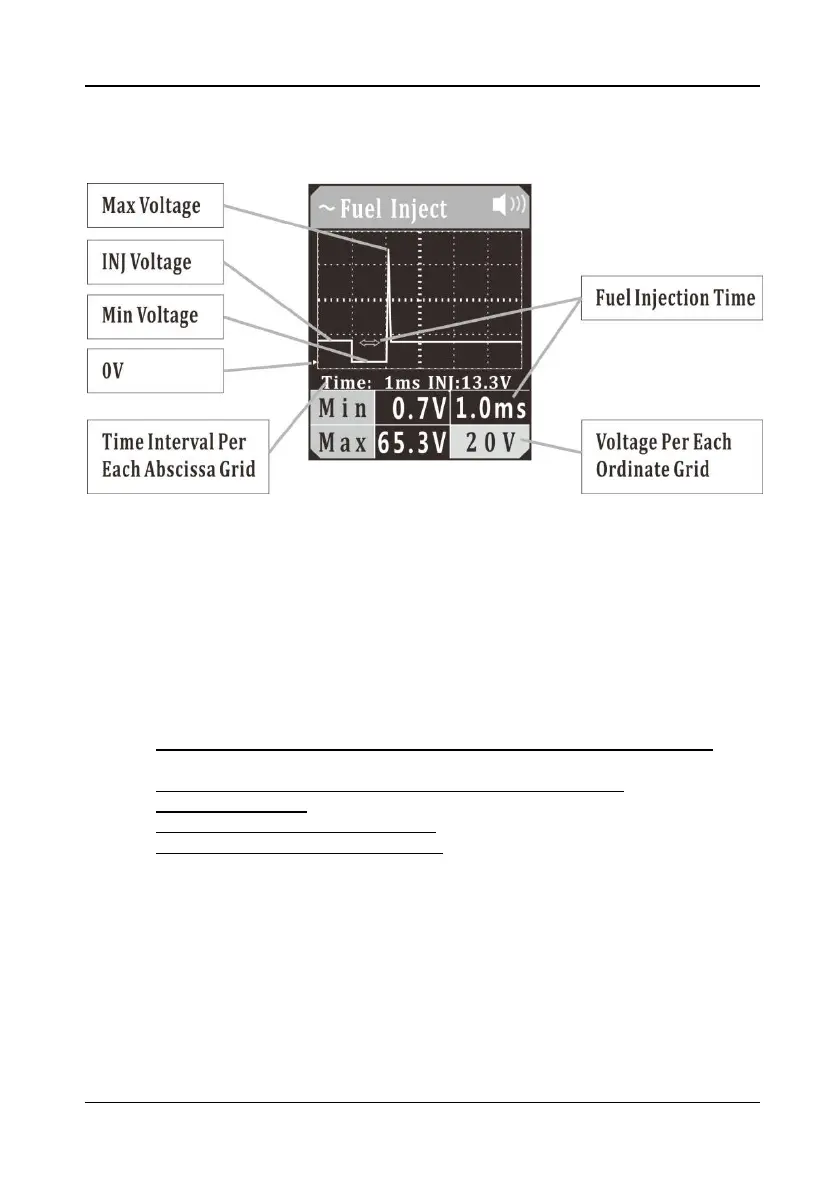
5.5 Fuel Inject
Figure 7
1)
Clip the red alligator clip to the battery positive pole; Clip the black alligator clip to
the battery negative pole.
2) Once the device is powered on, it will enter DC voltage test mode as default.
Short press the mode button to enter the menu, short press the down button to
place the cursor in the Fuel Inject mode, and short press the mode button to enter
the Fuel Inject waveform display mode.
3) Let the auxiliary ground wire be grounded, have the probe tip contact the negative
electrode of the injector control circuit, and the LCD display will read:
a) Maximum Reverse Induced Voltage Value of Fuel Injector Control Coil,
shown as Max (If it exceeds 35V, the red LED light will flash);
b) Minimum Ground Voltage Value When Fuel Injection Is ON, shown as Min;
c) Fuel Injection Time;
d) Fuel Injector Power Supply Voltage (INJ voltage), as shown in (Figure 7);
e) Display Signal Real-Time Waveform.
You can adjust the voltage per each ordinate grid in the waveform by pressing the
up button, and press the down button to adjust the time interval per each abscissa
grid.
(Figure 7) “time: 1ms” is the time interval indicated by each grid in the waveform,
which will vary with the sampling frequency.
The voltage value shown on the lower right corner is the voltage value per each
ordinate grid.
The green triangle mark indicates the position of 0V in the ordinate, as shown in
(Figure 7).
4) Long press and hold the mode button until the device switches to digital display
mode. It reads: