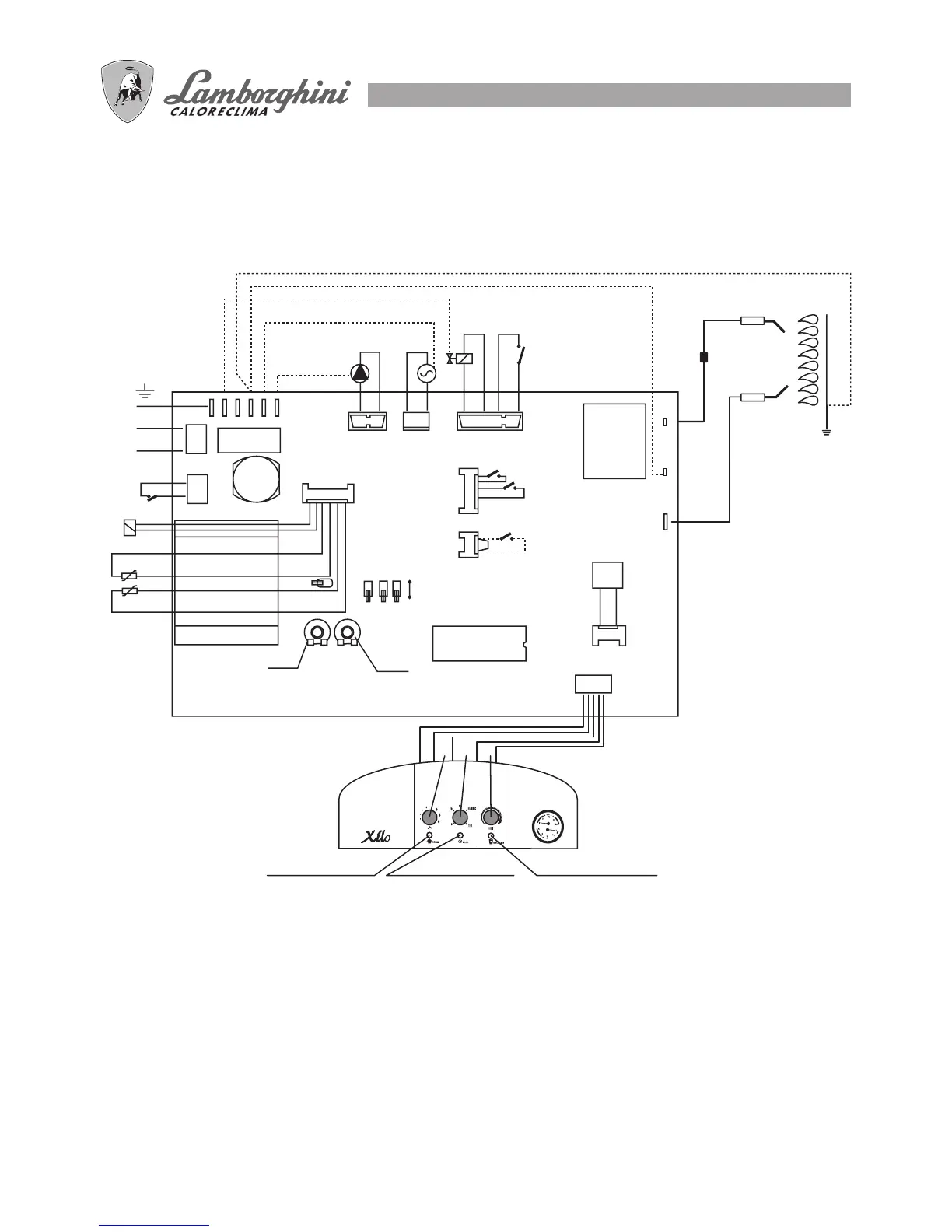
LEGEND
BM Modulating coil
CiR Heating circulator
EA Ignition electrode
EC Control electrode
F Fuse 2(A)
JP1 Methane/LPG selector
JP3 Post-circulation selector
JP4 Ignition limiting selector
JP5 Jumper to be cut for low temperature
L Phase 230 V 50 Hz
MP
H ot water priority micro pressure
switch
N Neutral
PA Air pressure switch
PS No-water pressure switch
RLA Slow ignition power adjustment
Rmax. Heating max. power adjustment
SR Heating sensor
SS Hot water sensor
TA Room thermostat (if any)
TL Limit thermostat (if any)
TST Safety thermostat
VG Gas valve
VN Fan
1 Heating potentiometer
2 Selector: Off
Summer
Winter
Reset
Test
3 Hot water potentiometer