21
5 Operating Control and Displays
NOTICE!
Signals of points 3 and 4 are "logical" signals and not "physical" ones. Background informa-
tion: Some signals may have more than one source (terminal, LSB, field buses, parameters).
Call up 2
nd
page of inputs
1. Use cursor keys to select the next page and press ENTER to confirm.
The display shows the 2
nd
page of inputs:
Call up 3
rd
page of inputs
1. Use the cursor keys to select the next page and press ENTER to confirm.
The display shows the 3
rd
page of inputs:
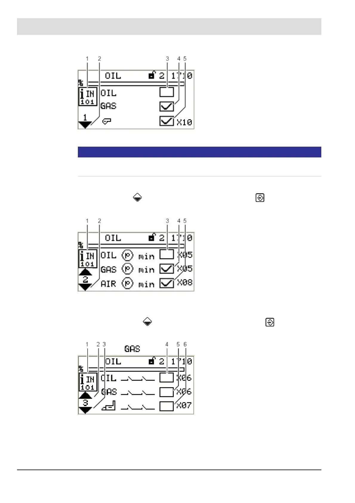
Fig. 5-14 Page 1 of inputs menu
1 Digital inputs pictogram
2 Jump to next page
3 Fuel selection oil [no]
4 Fuel selection gas [yes]
5 Burner start [yes] - terminal X10
Fig. 5-15 Page 2 of inputs menu
1 Digital inputs pictogram
2 Jump to next page
3 Oil pressure min present [no]
- terminal X05
4 Gas pressure min present [yes]
- terminal X05
5 Air pressure min present [yes]
- terminal X08
Fig. 5-16 Page 3 of inputs menu
1 Digital inputs pictogram
2 Jump to previous page
3 Jump to next page
4 Safety interlock chain oil closed [no]
- terminal X06
5 Safety interlock chain gas closed [no]
6 Safety interlock chain boiler closed [no]