37
6 Leakage Test for Main Gas Valves
6 Leakage Test for Main Gas Valves
6.1 Calculation Example
An (approximate) formula for calculating the leakage test monitoring facility is summarised be-
low:
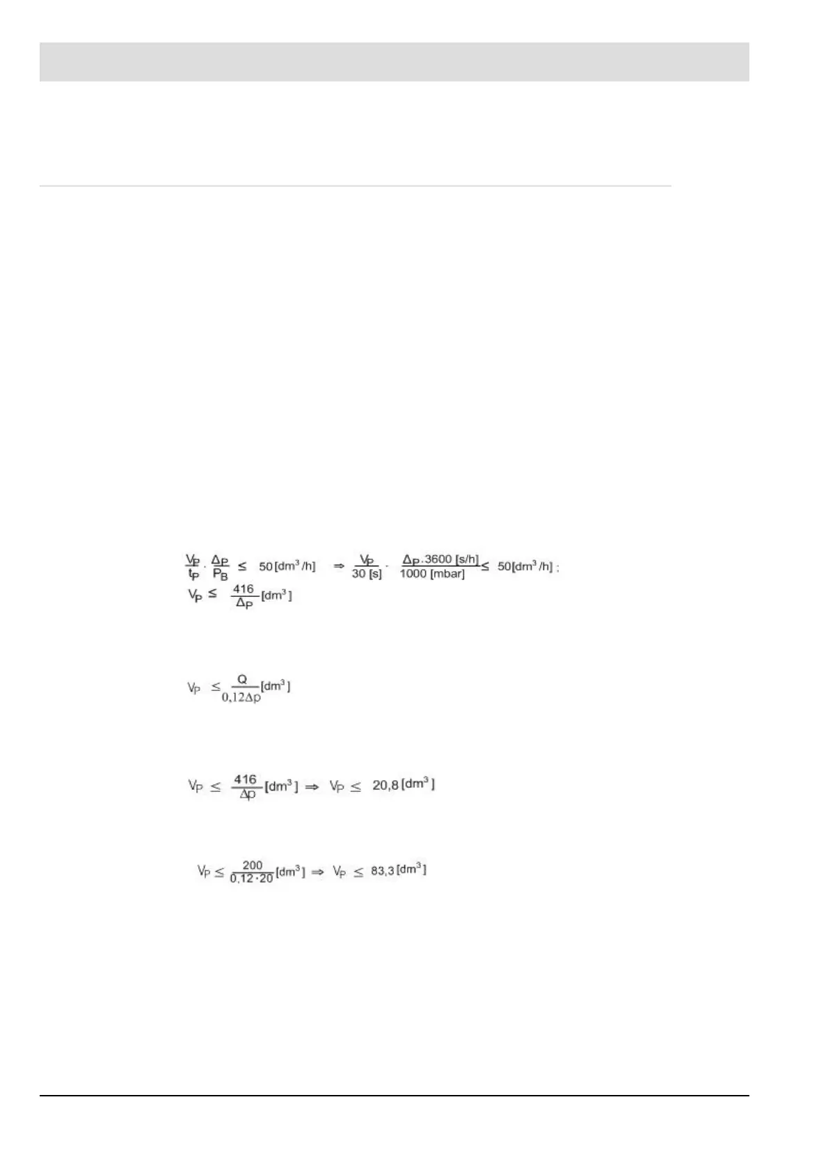
This means for a maximum gas flow rate of 50 m
3
/h the formula is:
Insert numerical value in mbar for Δp.
The formula for a gas flow rate of Q > 50 m
3
/h is:
Insert the numerical value in m
3
/h for Q and in mbar for Δp .
A. Assuming: ∆p = 20 mbar, gas flow rate < 50 m
3
/h
B. Assuming: ∆p = 20 mbar, gas flow rate = 200 m
3
/h
Definitions: GDW: gas pressure monitor
V1: gas-side safety shut-off device
V2: burner-side safety shut-off device
P
B
barometric air pressure < 1000 mbar
P
SU
lower GDW switching point (falling)
P
SO
upper GDW switching point (rising)
p = P
SO
- P
B
GDW switching difference
PG gas flow pressure (supply pressure before V1)
V
P
volume of gas line tested
V
L
leakage quantity
V
Lmax
maximum admissible leakage quantity (limit value)
t
P
testing time (30 s adjustable, default = 20 s)
i.e. the gas line you want to test must not
exceed 20,8 dm
3
, for being able to detect
the required leakage quantity.
i.e. the gas line you want to test must not
exceed 83,3 dm, for being able to detect
the required leakage quantity of 200 dm
3
/h.