- 17 -
If no flame signal is delivered in spite of an apparently correct functioning, check the
output contact (refer to 7.2).
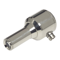
Alignment
IR- flame detectors should be installed / aligned in such a way that possible reflec-
tions form the combustion chamber are already largely suppressed by constructive
measures. A ball-and-socket joint for the alignment of the sensor to the flame is nor-
mally not required, since the optics of the flame detector is characterised by a wide
viewing angle.
UV- flame detectors should generally be used with one ball-and-socket joint only,
since the optics of the flame detector has a narrow viewing angle. That's why an opti-
mum alignment towards the flame is of utmost importance.
.
Optics
There are no special requirements for locking discs or similar components when using
IR- flame detectors. Small accumulations of dirt due to dust and similar materials are
mainly not critical for flame detection.
In UV- flame detectors, the requirements to locking discs are more strict. Make sure
to use a material that lets UV light pass (e.g. quartz) without problems. They are al-
ready contained in the LAMTEC-UV adjustable holding device (FS 19, FS 20, FV 19
and FV 20). Small accumulations of dust, water etc. are considerably more likely to
lead to problems in flame detection than IR radiation.
7.1.3 Adjustment
Sensitivity
If for the 1st burner start, there is no reaction, the sensitivity switch (flame amplitude)
can be set towards the right-hand stop position to allow a stable flame detection. The
positions 1 – 6 and/or 7 – 12 are allocated to the internal amplification of the flame
signal. Position 1 and/or 7 means lowest amplification / sensitivity as well as 6 and/or
12 highest amplification / sensitivity in the related sensitivity range.
Caution!
Make sure to react otherwise in a sufficient way to a flame not burning correctly or an
extinguishing flame next to the flame detector until successful switch-off test will have
been carried out.
After having carried out a correct burner adjustment, reduce the sensitivity again to
such an extent as to allow for a stable and safe operation. The measurable signals
should have at least 2 to 3 times the switching threshold value of 25 mV AC to al-
low a reliable recognition.
Alignment with adjustment function
To allow an optimum alignment of the compact flame detector towards the flame
(maximum flame amplitude), the intensity indicator of the device can be used by
activating the “Adjust“ function switch. The activation of the “Adjust“ switch
(ON position) suppresses the function of the
Serv. switch. The intensity indicator
now represents flame amplitude detected. If the intensity has already been set to
maximum in this function, reduce the sensitivity of the active sensitivity switch to such
a level that a reaction of the intensity indicator can be noticed, in order to find the best
possible view to the flame by alignment. After having completed the adjustment work
and/or before optimisation set the Adjust switch back to OFF.