- 12 -
6 Installation and assembly instructions
6.1 Assembly / Basic instructions
The radiation emitted by a flame contains a pulsating portion (flickering). This results
from the processes, which occur during combustion, the oscillation frequency (flame
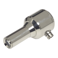
frequency) of which is used for monitoring. The compact flame detector is installed at
the burner at the viewing port provided for this and using the appropriate adjustable
holding device. Make sure that the burner flame remains perfectly visible through-
out the "Operation range of the furnace". To install a simple selective monitoring
device, the viewing port should be located in such a manner that the flame sensor de-
tects the flame root (near the burner mouth) of the burner flame to be monitored, and
that it cannot directly look into an adjacent flame or a flame located on the opposite
side. This is also of special importance as to background flames (coal, wood, waste).
The compact flame detector:
- is to be aligned in such a way as to cover the first third of the flame for single mo-
nitoring.
- has to cover the flame root area for a simple selection during the "Flame in" control
state (area of high flame frequencies), and during the "Flame out" state to only de-
tect the residual radiation caused by the "off-shoots" of the other flames in the
combustion chamber (area of low flame frequencies) or by reflection.
- If possible avoid to arrange the compact flame detector in parallel with the flame
axis, since in this position, a flame rupture can hardly be detected.
In order to reach a high availability and a high selection quality, it is very important to
place the compact flame detector at the appropriate location.
Make sure in every case that the aperture angle for the UV solutions is only about 8°.
That's why we recommend to use the FS 20 and/or FV20 adjustable holding device
(ball-and-socket joint), unless already in place. A correct alignment is of paramount
importance in particular in such cases where there is an additional viewing tube in-
side the burner or where the visibility of the flame is considerably restricted. The instal-
lation site must be easily accessible to allow a perfect observation of the visual opera-
tional controls even during operation of the furnace. When replacing the compact
flame detector, make sure to install a device having the same identification marking.
Make sure that the maximum admissible ambient temperature of 60 °C is not ex-
ceeded at the installation site. This applies in particular to radiant heat.
For the installation of an extension cable on site, make sure to use a separate,
shielded extensionable. Moreover, provide for good continuity of the shield and
make sure that the shield and functional earthing (FPE) are connected properly.
We recommend to lay the supply cable, including extension cable, on separate cable
trays to keep mains and control lines as well as high-energy power lines and equip-
ment separated from each other (e.g. ignition lines, ignition transformer, electrical mo-
tors, contactor). Moreover, avoid any parallel cable routing together with mains cables
in trays.
CAUTION!
Very high levels of electromagnetic radiated noise may result in sporadic problems in
flame detection, or may even avoid proper detection at all.