Do you have a question about the Lamtec F 200 K and is the answer not in the manual?
Outlines compliance requirements with the Equipment Safety Act for safe operation.
Specifies the intended use and standards for the F 200 K compact flame detector.
Details the application areas and furnaces for the flame detector.
Describes the physical construction and functional units of the flame detector.
Explains how the flame detector processes signals and its operational logic.
Illustrates the internal electrical components and signal flow of the detector.
Lists key characteristics like sensitivity and frequency ranges for different versions.
Details input/output parameters, voltage, current, and environmental conditions.
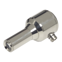
Provides guidance on physical mounting and alignment of the flame sensor.
Covers external installation, device connection, and related procedures.
Explains indicators, switches, and their functions for operation and adjustment.
Details the steps and checks required for initial setup and startup.
Guides on fine-tuning sensitivity and alignment for optimal flame detection.
Describes procedures to verify safety functions and fault responses.
Lists common issues related to interference and temperature affecting detection.
Identifies causes for flame detection issues during the ignition phase.
Outlines problems that can occur during normal operation of the detector.
Provides methods for diagnosing and resolving functional issues based on indicators.
Presents a visual guide for the step-by-step commissioning process.
Covers general remarks on cleaning and the need for integrated checks.
Diagram showing the controls and indicators for the F 200 K1 model.
Diagram showing controls and indicators for the F 200 K2 Ex-proof model.
Technical drawings with dimensions for F 200 K models in Zone 2 areas.
Dimensions and details for the Ex-proof F 200 K2 detector in Zone 1.
Dimensional drawing of the FG 24 Ex connection housing.
Wiring diagrams and pin assignments for the F 200 K1.
Wiring diagrams and pin assignments for the F 200 K2 Ex model.
Shows how to connect the flame detector with the Etamatic system.
Illustrates connecting the flame detector to an FMS system.
Describes the purpose and technical parameters of the FN 20 power supply unit.
Details the weather shield's purpose and features for outdoor installations.
Lists various holding devices for mounting the flame detector.
Provides instructions for installing the detector within a cooling air housing.
| Power consumption | Approx. 3 VA |
|---|---|
| Flame relay | 1 changeover contact (SPDT) |
| Output | 1 changeover contact (SPDT), 5 A / 250 V AC |
| Suitable burners | Gas, oil, and dual-fuel burners |
| Operating Temperature | -20 to +60 °C |