- 38 -
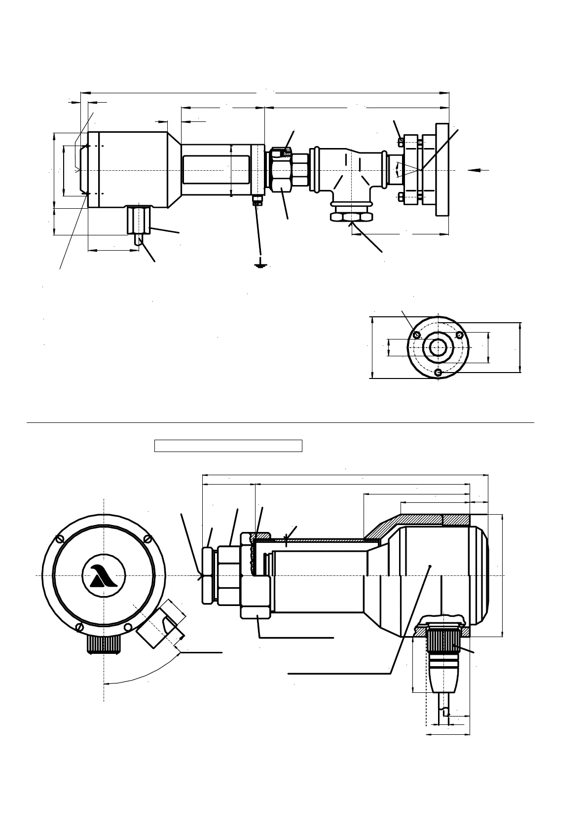
View of the FV 20-10 with F 200 K Ex
*
G2; 12 tief
*
G1
Ø
11,5
Ø
110
Ø
27
Ø
55
Ø
89
Ø
4 x cylindrical bolts M5
ISO 4762 (DIN 912)
Ø
6
View
A
S
W
10
4
0
°
79
41
Operating state
indicator
11
67
200
Stopper disk
detachable
±5
±5
Ø
Connecting cabel
Ø 8 mm, 3 m long
cofiguration as in
F 200 K
Cable entry not
detachable
Sensor surface:
withe aluminium RAL 9006 matt
Cylindrical bolt DIN 84
Connection core section 2,5...6 mm²
Sleeve nut SW 53
Thread G 1½
Sensor connection
with purging air
separation
Connectors-cylindrical
pipe threads DIN ISO 228/1
* for pipe connector with thread
only on special order
Inner thread G ½"
purging air connection
Ball-and-socket-
joint ± 20°
in two levels
A
299
60
90
32
60
13.3.5 FS 50 (without ball-and-socket-joint and cooling air housing)
Purchase order no.: 659 R 6109
ø100
Display
45
175
86
56
(< 15)
Mounting position of the flame
sensor electrically insulated
Sealing ring 56x42x2
Detachable connection 8 Kt SW 66
(Lens cleaning)
22
45
4
5
°
Cooling air
connection
(galvanic isolation)
36
8 Kt SW 48
6Kt SW 46
Pipe connector
(boiler) Rp1"
Cable connector
with screwed
connection
ca. 235
3x setting screws
M6 - nylon
Rp ½
"
20
ø < 10