- 22 -
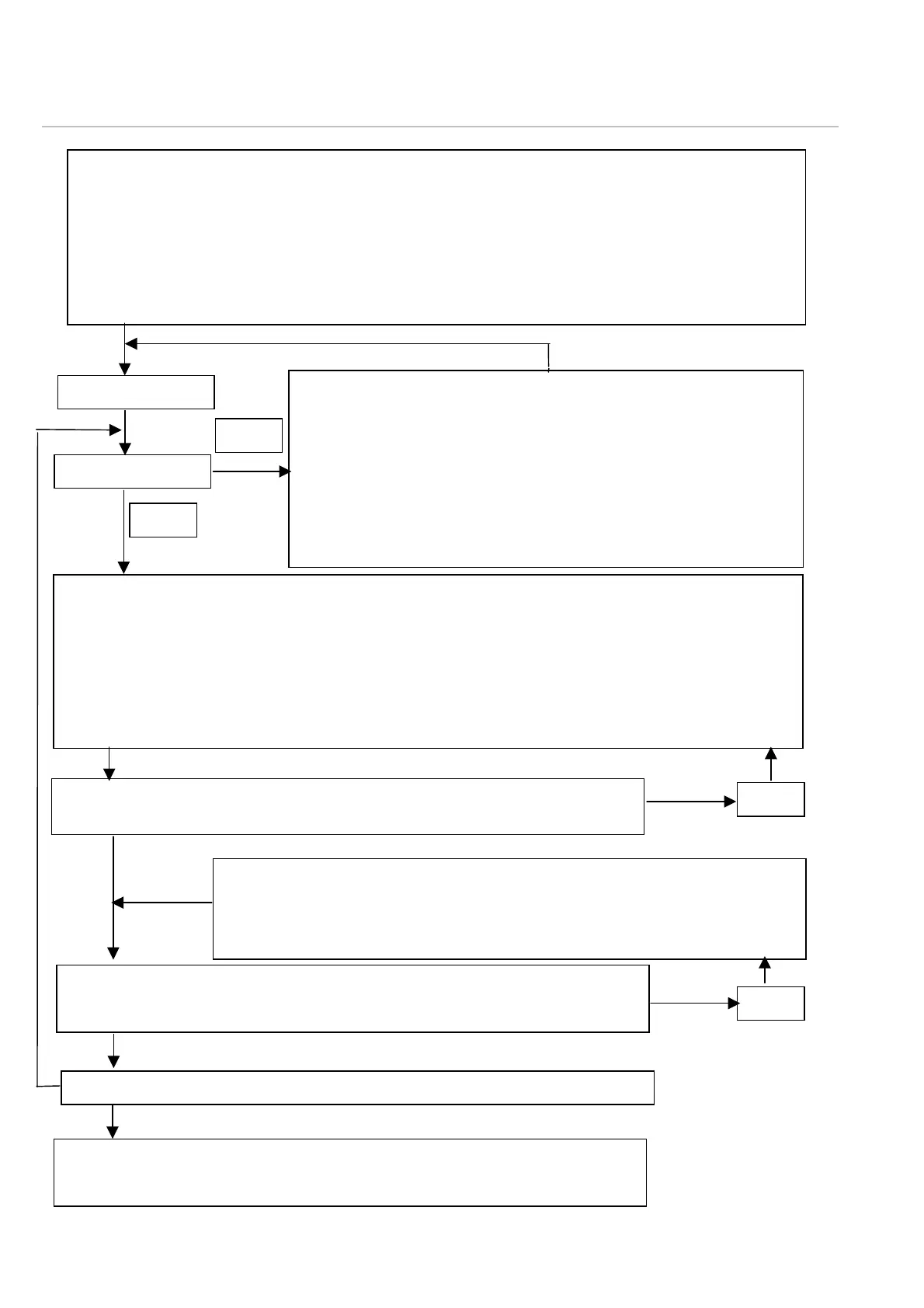
7.3 Commissioning flow chart
Settings to be carried out before burner commissioning
- Check all electrical connections for presence and tight installation
Verify cable laying, including continuous shielding and FPE connection
- Compact flame detector
Check the compact flame detector for proper functioning (section 7.1.2)
Orient the compact flame detector to the 1st third of the main flame or pilot flame to be
monitored
The flame must be visible throughout the operating range
Burner start
Flame „In“
Check if there are sufficient visibility of the main flame or pilot flame in
the viewing zone of the flame detector, if required change the burne
adjustment.
Check the viewing port for accumulation of dirt
Check the compact flame detector for proper alignment
- for UV: maximise the signal strength by readjusting the alignmen
and by consequently increasing the sensitivity if required
- for IR: increase the sensitivity step by step by turning the selecto
switch towards the right-hand stop
Optimisation of the set values
for IR: in order to obtain an optimum between detectability of the flame and suppression of possible
reflections (e. g. glowing refractory lining), turn the related sensitivity selector switch of the compac
flame detector towards the right-hand stop only to such a point that the evaluated intensity indication
is still present without signal ruptures / lowering.
for UV: at first maximise the signal strength by optimising the detector alignment towards the flame, i
required towards the pilot flame if the pilot flame and main flame are jointly monitored. Measure the
signal voltage at the measuring output or use the “Adjust“ function (section.7.1.4), after this set the
sensitivity selector switch if necessary.
Verification measures Flame detection
- in all load stages of the burner, the flame is reliably detected
Check again the set values by a burner re-start
no
es
no
Verification measures Flame „OUT“ message
- When carrying out the burner switch-off test, the flame „OUT“ message
relating
no
- Check the viewing situation (e. g. direct view towards the glowing refractory
lining or adjacent flames)
- Reduce sensitivity if required
- Increase the lower frequency limit (for F 200 K2 only)
- Use the start-u
su
ression in the ran
e between 50 ... 100 %
section 7.1.4
Set values, measured values and manufacture number of the compact flame
detector, and note down the approximate maximum ambient temperature in the IB
documents.