- 7 -
The cable provides for the following connections:
- Infeed of auxiliary energy
- Connection of the operational earthing FPE
- Connection of external power circuits to a failsafe change-over contact to control
the control states "Flame out" and "Flame in"
- Connection of the intensity measurement output
- Connection for an external sensitivity change-over, only for F 200 K2
- Connection of the screen via the plug enclosure
The layout of the operational controls is represented in section 10.
3.4 Mode of operation
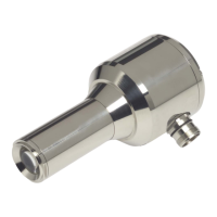
The compact flame detector converts the flame radiation pulses of the burner flame
into electrical signals. These representative signals are routed to an electronic
changeover switch, which alternately applies them to one of the independently work-
ing processing channels, where the signals are digitised. This reduces the initial signal
quantity to the information "pulse period" (information carrier: pulse frequency of the
flame radiation). The digitised signals are compared with the related reference signals
by means of a digital frequency evaluation unit. This makes sure that only those flame
signals that are within the pre-selected frequency transmission range will be included
in a continued processing, irrespective of their original amplitude. A control switch (for
the F 200 K2 only) located below the removable cover allows to change the lower fre-
quency limit if required. After evaluation, the flame signal is routed to the switching
amplifier, which also controls the related shut-down time. A safe monitoring of the
antivalent control states as well as the response and shut-down periods is performed
at the output of the signal processing channels, before an activation of the output re-
lays at the end of each signal processing channel is carried out. Antivalence faults and
deviation in time delays going beyond the admissible limit values result in the control
state "Flame out". The control states “Flame out“ and “Flame in“ are indicated on the
rear side of the device by means of a red and/or green LED, the change-over between
the two signal processing channels being indicated by pulsation of the green LED dur-
ing the “Flame in“ control state. Moreover, one or two six-step control switches provide
for a sensitivity adjustment to adapt the system to the flames to be monitored, this be-
ing indicated by means of a six-step chain of green LEDs designed to be the device's
flame intensity indicator.
Miscellaneous
Self-monitoring principle
Signal processing is carried out by means of two transmission channels working inde-
pendently of each other and alternately triggered. The output levels are permanently
checked for antivalence within a given time grid.
Parameter adjustment, furnace type → Monitoring equipment
The turning knob controls of the F 200 K1 / F 200 K2 compact flame detectors allow to
set 6 to 12 sensitivity levels, the F 200 K version providing an increased sensitivity
level in range II. A six-step green LED indicator indicates the evaluated flame intensity
on the rear side of the device. The transmission range of the digital flame frequency
evaluation allows for signal passage between10 ... 190 Hz (F 200 K1) and/or 10 / 30 /
45 ... 190 Hz (F 200 K2).