19
5 LAMTEC SYSTEM BUS (LSB)
5 LAMTEC SYSTEM BUS (LSB)
5.1 Jumpers, LED, Fuses and Terminals
5.2 Function
NOTICE
The data of the LT2 is only transferred by LAMTEC SYSTEM BUS if the device is set to MEAS-
URING and not to MAINTENANCE or ERROR.
If the communication works properly LED 1 and LED 2 are flashing.
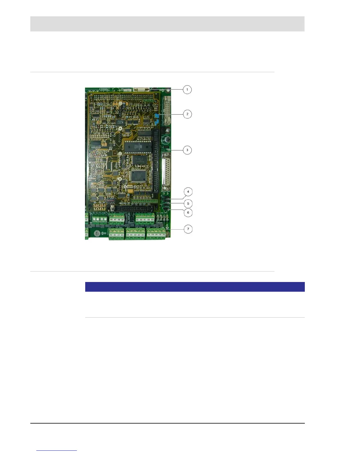
Fig. 5-1 LT2 assignment
1 F6 - T315 mA 5 VDC - LSB
2 BR12, BR13 → position ’C’ - CAN
3 BR105 → position 2-3 (left)
4 LED1 – green → RxD from LSB *
LED2 – yellow → TxD from LSB *
5 BR102 – BR104 position 1-2 (left)
base board V.03 and higher
6 BR101–120 termination resistor LSB,
→ position 1-2 (right)
without terminating resistor
→ position 2-3 (left)
with terminating resistor
7 terminal 71 → CAN-GND
terminal 74 → CAN-H
terminal → CAN-L
* LED flickering