20
6 Commissioning/Decommissioning
6 Commissioning/Decommissioning
6.1 Preliminary Works
6.1.1 The LT2 Lambda Transmitter's Display and Operating Elements
The LT2's operation and the display of measured values, operational and error messages take
place by the (optional) display and operating unit, or by a PC in combination with the Remote
Display Software. The LT2 itself has only limited operating capabilities, which do not allow LT2
to display or process all the functions necessary for operation, maintenance and servicing.
6.1.2 Monitor Output
The monitor output (terminals 31 (-) and 32 (+)) makes it possible to connect a multimeter for
example. The device indicates the following values by the monitor output:
–O
2
measured value
– Probe voltage [U]
– The measuring cell's AC internal resistor [R
i
]
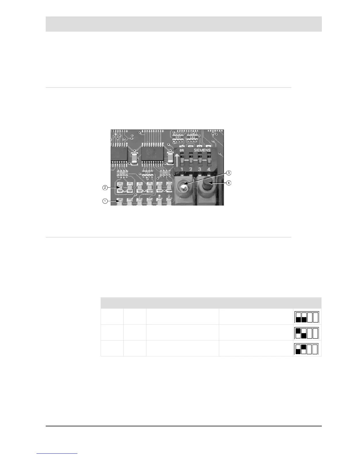
DIP switch processor card
Input resistance of the connected measuring device greater than 10 k.
Fig. 6-1 Internal display and operating elements on the processor
board
1 Display of operating
mode
2 Warning /
Fault display
3 Maintenance switch
4 Multifunction key
SW 1 SW 2 Monitor output function
OFF OFF O
2
measured value 0 ... 2.5 V = 0 ... 25 % vol O
2
ON OFF O
2
probe voltage (U-O
2
) 0 ... 2.5 V = 0 ... 250 mV
OFF ON O
2
cell’s internal resistance 0 ... 2.5 V = 0 ... 250