23
6 Commissioning/Decommissioning
Mounting steps
1. Drill or burn out a hole in the flue channel, with diameter G 1¼ “.
2. Firmly weld a half-collar, interior thread G 1¼ “tight” at the measurement site.
NOTICE
Apply the collar’s thread, the PIF’s thread and the clamping ring with anti-size-paste type
650R1090. This avoids the seizing and guaranties a smooth dismounting of the LT2 probe.
3. Screw in the PIF without probe, and tighten.
4. Seal the PIF aperture with a blank plug if necessary.
5. Insert GED into probe and tighten
NOTICE
Install the probe just before commissioning. In a built-in state, the probe should always be
heated.
This prevents moisture from settling on the measuring cell, which, among other things, can
cause measuring errors and could destroy the probe.
NOTICE
During the installation of the probe and later operation, ensure that the probe does not come
into contact with oils, greases, or boiler cleaning agents.
Poisoned and/or dirty probes can be detected by an air voltage of -20 ... -30 mV.
6. Install, position and tighten probe in PIF after commissioning.
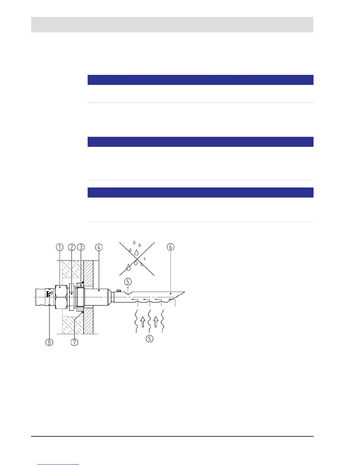
Fig. 6-2 Correct Probe installation with GED
1 Union nut
2 Threaded connection (position 1+2 = Probe
installation fitting (PIF) type 655R1010)
3 Welding socket
4 Probe
5 Flue gas
6 Gas extraction device
7 Welded
8 Rating plate