26
6 Commissioning/Decommissioning
NOTICE
Calibration is displayed
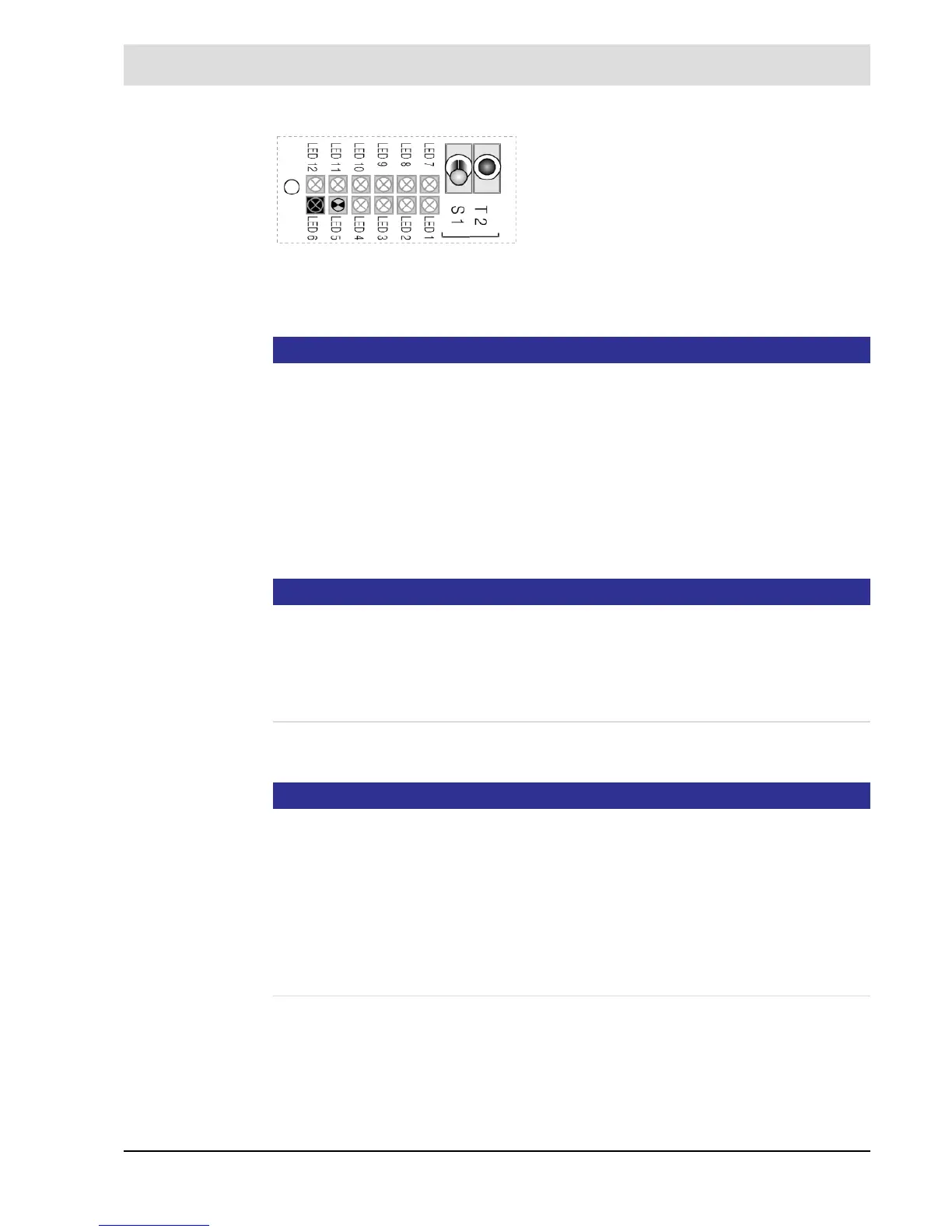
LED 6 OPERATION is ON
LED 5 MEASUREMENT is flashing
• Wait for offset calibration to be finished.
Flashing has stopped.
• Enter probe temperature from the test protocol, parameter 141 ’customer access level’;
alternatively see separate manual in
– Display and operating unit (optional)
– Remote display software (optional)
• Exit MAINTENANCE
NOTICE
"Probe temperature T"
The LT2 Lambda Transmitter and LS2 Lambda Probe are not adjusted to each other. The LS2
Lambda Probe is subject to production dispersion, which can be compensated by offset cali-
bration and probe temperature. A probe calibration with test gas is not necessary.
The probe temperatures determined by the end test can be found in the test protocol (which
is part of the delivery).
• Install probe as descriped in chapter 6.3 Return to Service.
NOTICE
When installing or operating the probe, ensure that the probe does not get into contact with
oil, grease or boiler cleaning materials.
This does not apply only to the cell, but also to the connector region!
The thread and the clamping ring should be treated with mounting paste type 655R1090 to
prevent for seizing.
Poisoned or contaminated probes can be identified by an air voltage of -20 …- 30 mV.
The probe must always be in operation when it is installed. This avoids the precipitation of
moisture on the measuring cell, which in certain cases can lead to erroneous measurements
and to the probe's destruction!
Fig. 6-7 Multifunction key T2
After a 10 minutes heating phase, the probe voltage
would be stabilised to values between -5 and -15 mV
and the measuring cell (R
i
probe) internal resistance
would be stabilised to values below 100, for new
probe below 20 . Are positive values displayed in
air, the probe’s polarity is reversed. Swap probe con-
nection on terminals 33/34.
Proceed with offset calibration alternatively by using
display and operating unit in [cal] or the multifunc-
tional key T2 (hold for more than 3 seconds in
MEASURING mode).