7
Installing CO
2
Supply
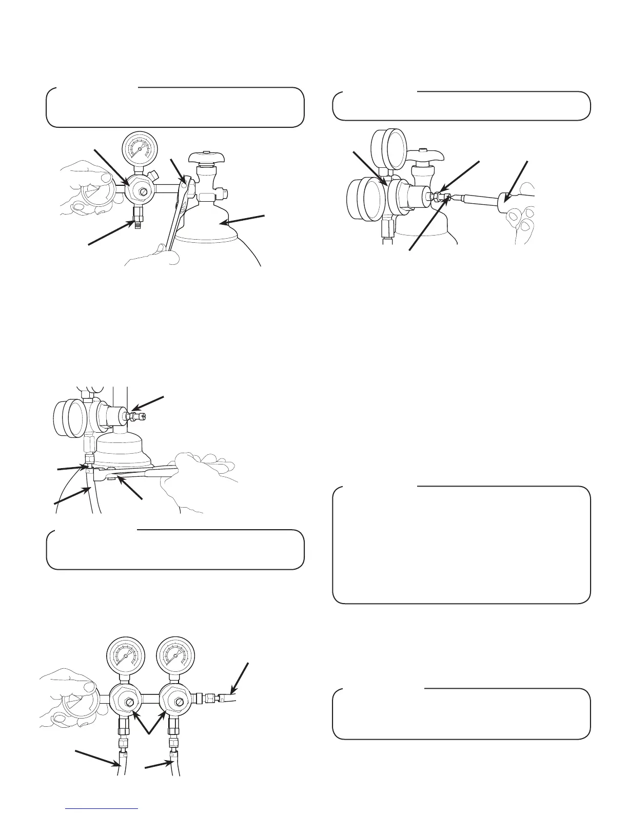
1. Connect high pressure CO
2
regulator assembly to CO
2
cylinder or bulk system.
2. Connect a 1/4” nut, stem and seal to CO
2
regulator outlet.
3. Route appropriate tubing from the low pressure CO
2
regulator manifold location to the 1/4” nut, stem on the high
pressure CO
2
regulator attached to source and connect
tubing.
4. Connect tubing routed from the CO
2
inlet at the unit to one of
the low pressure CO
2
regulator manifold outlets.
5. Connect tubing routed from the tee at the syrup pumps to
the second outlet of the low pressure CO
2
regulator manifold.
6. Using a wrench, loosen lock nut on the regulator adjustment
screw of the high pressure CO
2
regulator connected to the
source, then using a screwdriver back out lock nut screw all
the way.
7. Repeat Step 6 for both low pressure CO
2
regulators on the
regulator manifold routed to the unit and the syrup pumps.
- Thread regulator nut on to tank, then
tighten nut with wrench
A. CO
2
Regulator
B. Outlet
C. Wrench
D. CO
2
Supply
A
B
C
D
Before installing regulator, assure that a seal (washer
or o-ring) is present in regulator attachment nut.
! ATTENTION
A. CO
2
Regulator
B. 1/4” Nut, Stem & Seal
C. Line to CO
2
Regulator
Manifold
D. Oetiker Pliers
A
B
C
D
A dedicated CO
2
regulator is required to supply the CO
2
inlet at the unit as well as to all syrup pumps.
! ATTENTION
A
B
C
D
A. Line to Dispenser
B. Line to Syrup Pumps
C. Line to CO
2
Regulator
D. CO
2
Regulator Manifold
DO NOT TURN ON CO
2
SUPPLY AT THIS TIME
! WARNING
A. CO
2
Regulator
B. Screwdriver
C. Loosened Lock Nut
D. Regulator Adjustment Screw
A
BC
D
Dispenser Setup
1. Turn on water source.
2. Open the pressure relief valve located at the front of the unit,
by ipping up on the valve cap lever. Hold open until water
ows from the relief valve then close (ip down) the relief
valve.
3. Verify all Bag-In-Box contains syrup and check all
connections for leaks.
4. Place enough ice in the ice bin to ll approximately 1/2 of the
bin before plugging in the unit.
5. Connect unit power cord to grounded electrical outlet.
The dispenser must be properly electrically grounded
toavoidseriousinjuryorfatalelectricalshock.The
power cord has a three-prong grounded plug. If a
three-hole grounded electrical outlet is not available,
use an approved method to ground the unit. Follow all
localelectricalcodeswhenmakingconnections.Each
dispenser must have a separate electrical circuit. Do
not use extension cords. Do not connect multiple
electrical devices on the same outlet.
! WARNING
6. Test the motor operation by pushing the ice chute lever until
agitator motor begins to turn.
7. Activate each valve to ensure a good ow of water is
achieved.
8. Ensure pump deck is turned OFF before turning on CO
2
.
Failure to disconnect the motor power supply will
damage the carbonator motor, the pump and void the
warranty.
! ATTENTION