12: Connections and Pinouts
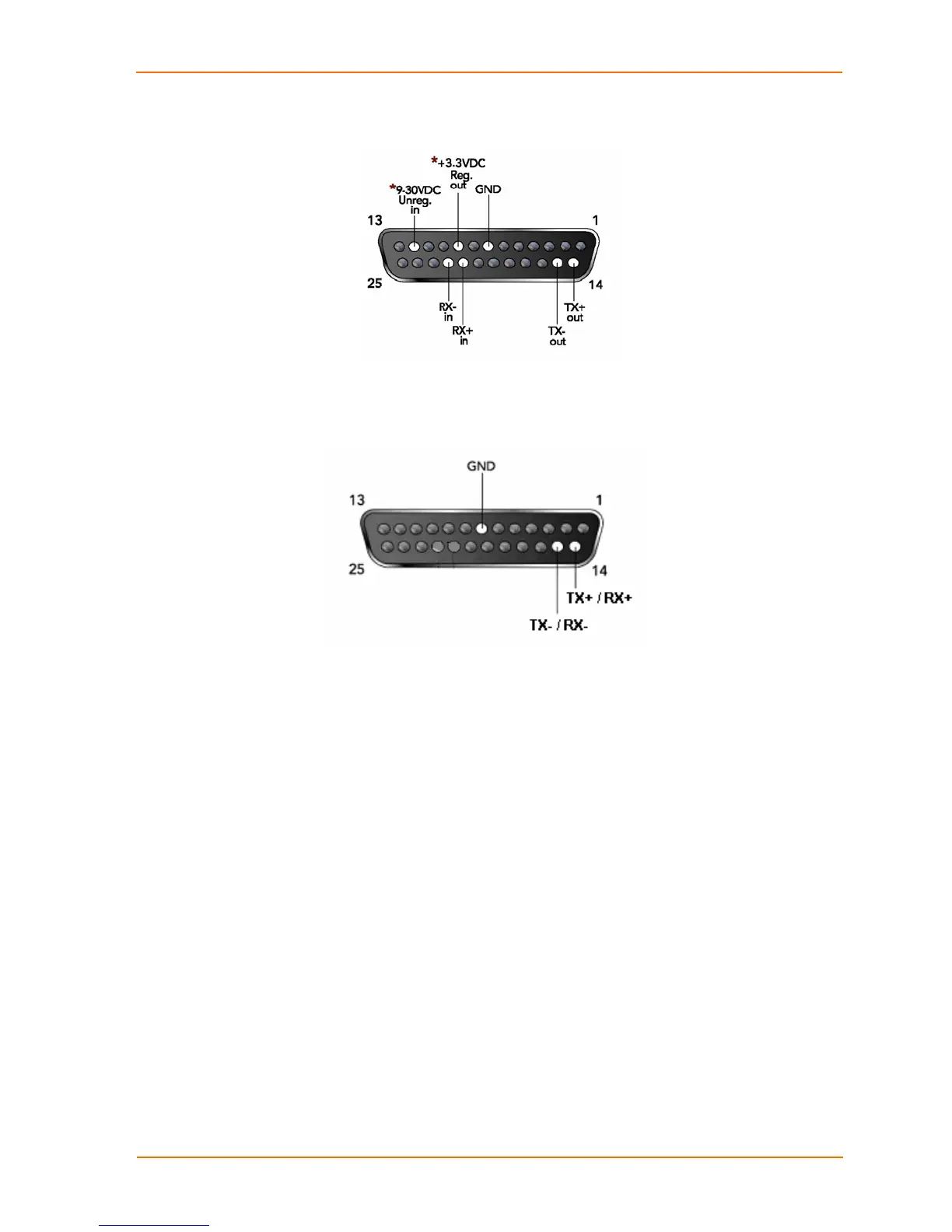
Figure 12-3. DB25 Female Interface RS422 (4 wire mode)
*Optional power connection for non-POE unit.
Figure 12-4. DB25 Female Interface RS485 (2 wire mode)
Modem Cable
When attaching the DB25 of the UDS to the DB9 com port on a PC, use a
standard straight-through serial cable (Lantronix Part No. 500-163). The
figure below shows the pinouts for a DB25 to DB9 straight-through cable,
often referred to as a "Modem Cable".
To configure the UDS using the DB9 serial port, you need only pin out the
TXD, RXD, and GND signals.
UDS1100 User Guide 72

 Loading...