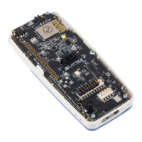
iCE40 Ultra Breakout Board
Evaluation Board User Guide
© 2014-2020 Lattice Semiconductor Corp. All Lattice trademarks, registered trademarks, patents, and disclaimers are as listed at www.latticesemi.com/legal.
All other brand or product names are trademarks or registered trademarks of their respective holders. The specifications and information herein are subject to change without notice.
12 FPGA-EB-02034-1.2
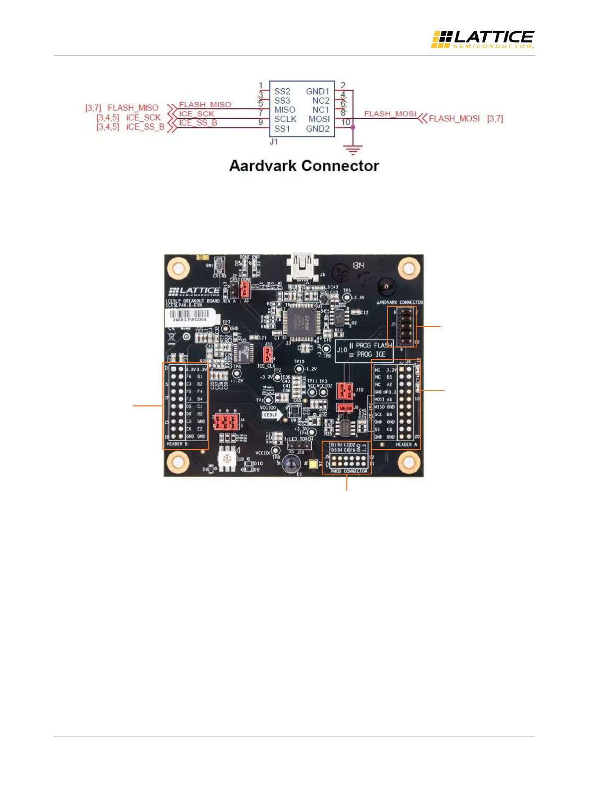
Figure 9.4. J7 Header B Breakouts
The breakout headers and test connectors are shown in Figure 9.5.
J6 – Header A
J7 – Header B
J1 – Aardvark SPI
emulator connector
J5 – PMOD Connector
Figure 9.5. Breakout Headers

 Loading...