iCE40 Ultra Breakout Board
Evaluation Board User Guide
© 2014-2020 Lattice Semiconductor Corp. All Lattice trademarks, registered trademarks, patents, and disclaimers are as listed at www.latticesemi.com/legal.
All other brand or product names are trademarks or registered trademarks of their respective holders. The specifications and information herein are subject to change without notice.
6 FPGA-EB-02034-1.2
1. Introduction
This guide describes how to begin using the iCE40 Ultra™ Breakout Board, an easy-to-use platform for demonstrating
the high-current LED drive capabilities of the iCE40 Ultra FPGA. Along with the evaluation board and accessories, this
kit includes the pre-loaded LED Driver Demo that demonstrates driving the RGB LEDs with a PWM circuit. In addition,
most of the device's I/O balls are accessible through one of the several header locations on the board, facilitating rapid
prototyping of user functions.
The contents of this user guide include demo operation, top-level functional descriptions of the various portions of the
evaluation board, descriptions of the onboard connectors, shunts, a complete set of schematics, and the bill of
materials for the iCE40 Ultra Breakout Board.
Note: Static electricity can severely shorten the lifespan of electronic components. Be careful when handling the iCE40
Ultra Breakout Board as to not damage it from ESD.
2. Features
The iCE40 Ultra Breakout Board includes:
iCE40HX-8K Evaluation Board – The iCE40 Ultra Breakout Board features the following onboard components and
circuits:
iCE40 Ultra (iCE5LP4K-SWG36) device in a 36-ball WLCSP package
Example of a board using this 0.35-pitch WLCSP package
High-current LED output
Infrared transmit
iCE40 Ultra Current Measurements
Standard USB cable for device programming
RoHS-compliant packaging and process
Pre-loaded Demo – The kit includes a pre-loaded demo to control the onboard RGB LED in conjunction with a
software run user interface.
USB Connector Cable – A mini B USB port provides power, a programming interface and communication for the
software RGB LED user interface to the iCE40 Ultra SPI port.
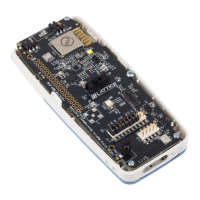
Figure 2.1 shows the top side of the iCE40 Ultra Breakout Board indicating the specific features that are designed on
the board.