iCE40 Ultra Breakout Board
Evaluation Board User Guide
© 2014-2020 Lattice Semiconductor Corp. All Lattice trademarks, registered trademarks, patents, and disclaimers are as listed at www.latticesemi.com/legal.
All other brand or product names are trademarks or registered trademarks of their respective holders. The specifications and information herein are subject to change without notice.
FPGA-EB-02034-1.2 13
10. RGB LED Demonstration Design and User Interface
The iCE40 Ultra Breakout Board can demonstrate a complete controller for an RGB LED.
To run the demonstration:
1. Ensure that the RGB LED user interface is installed.
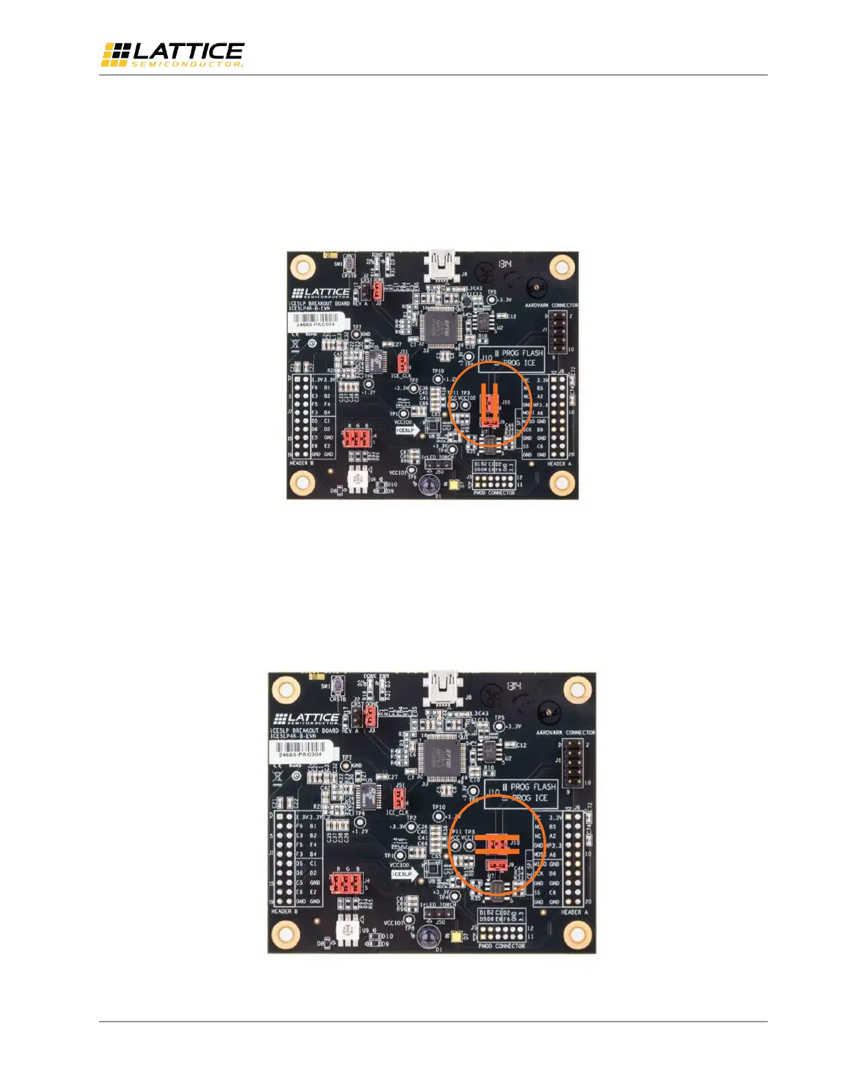
2. Make sure the jumpers on J10 are both in the vertical position. This is the default pins 1-3 and 2-4 shorted.
Figure 10.1. SPI Flash Selection for J10 (Vertical)
3. Connect the iCE40 Ultra breakout board through USB cable to a PC or MAC.
4. After the iCE40 Ultra device has initialized and the RGB LED is illuminated RED, change the J10 jumper positions to
horizontal, shorting pins 1-2 and 3-4. This is required to allow the USB port to communicate with the iCE40 Ultra
device.
Figure 10.2. iCE40 Ultra Selection for J10 (Horizontal)

 Loading...