iCE40 Ultra Breakout Board
Evaluation Board User Guide
© 2014-2020 Lattice Semiconductor Corp. All Lattice trademarks, registered trademarks, patents, and disclaimers are as listed at www.latticesemi.com/legal.
All other brand or product names are trademarks or registered trademarks of their respective holders. The specifications and information herein are subject to change without notice.
8 FPGA-EB-02034-1.2
3. iCE40 Ultra Device
The board features an iCE5LP4K FPGA with a 1.2 V core supply. The device is packaged in a 36-ball WLCSP. For a
complete description of this device, refer to iCE40 Ultra Family Data Sheet (FPGA-DS-02028).
4. Software Requirements
You should install the following software before you begin developing designs for the board:
Lattice iCEcube2 2014.04 (or higher)
Diamond Programmer 3.2 (or higher)
These software are available at the Lattice website Design Software and IP page. Make sure you log in to
www.latticesemi.com. Otherwise, these software downloads are not visible. It is also recommended to download the
RGB LED software user interface which interfaces with the iCE40 Ultra Breakout Board. This user interface allows you to
control the RGB LED for color, brightness, blinking, and breathing. Download the PC or MAC version of the user
interface at www.latticesemi.com.
5. Demonstration Design Shunts
Lattice provides the RGB LED Driver Demo design programmed in the board. The RGB LED Driver Demo used in
conjunction with the software user interface illustrates the use of a PWM driver controlling the LEDs on the board.
Below is a description of the control jumpers for each LED.
The RGB LED transition colors
J4 can be used to probe RGB LED (default shunted). If you remove J4, the RGB LED does not light up.
The IR LED is controlled when a shunt is placed across J50 pins 1-2.
The Bar Code LED is controlled when a shunt is placed across J29 pins 2-3 (default shunted).
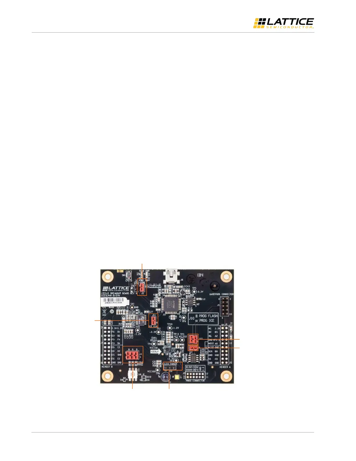
Figure 5.1 shows the default board shunt locations.
J3 - Enable DONE LED
J9 – Isolate
SPI Flash CSn
J50 – Selects-
HP LED device
(IR or Torch)
J51 – Enable-
12 MHz clock
J4 – - RGB
Shunts
J10 – Program
SPI Flash or iCE5LP
Figure 5.1. Default Shunt Locations