LAUNCH X-431TOP User’s Manual
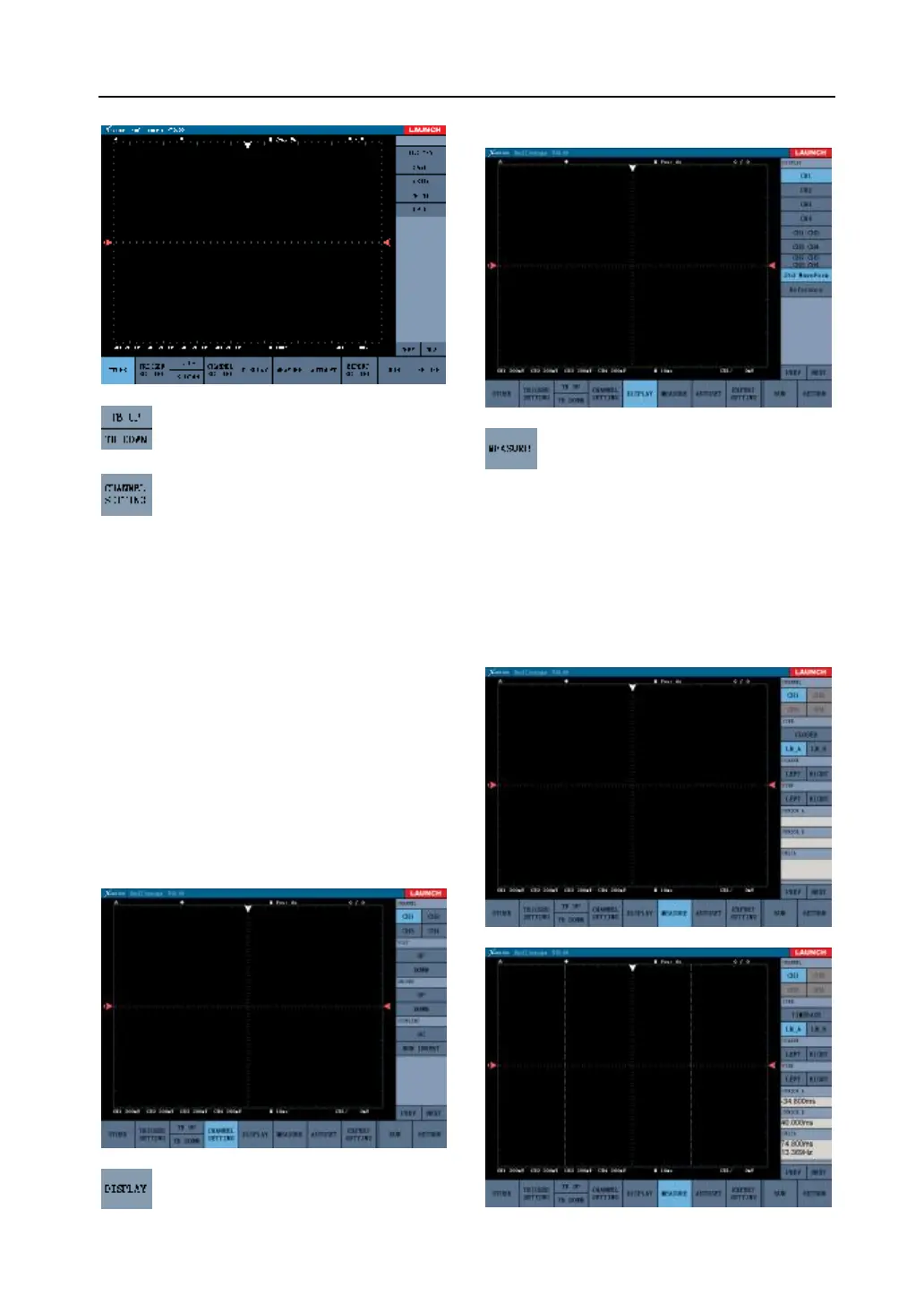
Fig. 3-7
Regulate the time base value; time base:
the time value of the each case level length.
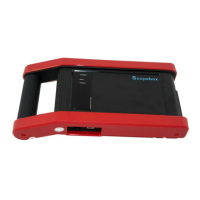
Channle parameter setting. Fig.3-8
shows the “ channel “ setting interface.
Channel: the current setting channel is lit.
Voltage: the voltage value of the each case
vertical length with regulation by [add] and
[decrease]. The display value in the right-down
corner display the regulation value.
Ground:the 0V voltage position of oscilloscope
display with regulation by [up]and [down].
Coupling mode: (AC ~ DC)and (positive ~
inverse). DC coupling: for measuring AC and DC
signal; AC coupling: only let the AC portion
transit .
Note: When the numerical value and cursor
don’t occur, please choose the relevant
channel display on the “display setting”.
Fig.3-8
Display mode setting with 7 display
modes can be chosen. See fig. 3-9.
Fig. 3-9
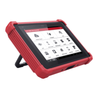
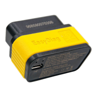
Measure voltage and time base. Click
“measure” in fig 3-10 to enter. The right column:
Channel- choose the channel to measure and the
current channel is lit.
Option- choose the option to measure .The time
base and voltage can be measured(see fig.
3-11).
Corase tuning: to move 4 scales by once click.
Fine tuning: to move 1/5 scale by once click.
Fig.3-10