LAUNCH X-431TOP User’s Manual
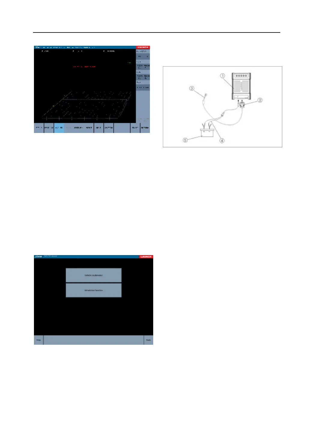
图 4-27
[signal]: Click “ INC” or “DEC” to increase or
decrease the signal.
[X axial]: Click “ IN” or “OUT” to zoom in or zoom
out the proportion of X axial.
[Y axial]: Click “ IN” or “OUT” to zoom in or zoom
out the proportion of Y axial.
[MOVE]: Click “ UP”,”DOWN”,”RIGHT” or “LEFT”
to move the waveform.
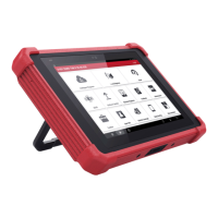
Vehicle sensor
Fig. 3-28
The function of vehicle sensor includes vehicle
multimeter and simulation function.
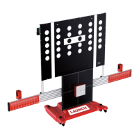
Connection Description
Vehicle sensor diagnosis diagram
1-X-431TOP terminal
2-sensor test cable
3-test probe
4-battery cable w/two clips
l Connect the sensor test cable to the 26PIN
port of the X-431TOP terminal.
l Connect the power supply to the DC port of
the X-431TOP terminal.
NOTE:
1. From cigar lighter: insert one end of the
cigar lighter cable into the lighter socket
in vehicle and connect the other end to
the DC power connector of X-431TOP
Terminal.
2. From double-clip power cable: connect
one end of the double-clip power cable to
the positive & negative battery and the
other end to the DC power connector of
the X-431TOP Terminal.
3. From power patch cord: connect one end
of the power patch cord to the 100-240V
AC socket and the other end to the jack
of the on-off power. And connect the
power jack to the DC power connector.
Vehicle Multimeter
In the interface as shown in fig. 3-29, voltage,
resistance and frequency can be tested.