A
A
C
C
S
S
8
8
0
0
6
6
D
D
i
i
g
g
i
i
t
t
a
a
l
l
A
A
C
C
S
S
e
e
r
r
v
v
o
o
d
d
r
r
i
i
v
v
e
e
M
M
a
a
n
n
u
u
a
a
l
l
R
R
e
e
v
v
1
1
.
.
0
0
Tel: (86)755-26434369 40 Website: www.leadshine.com
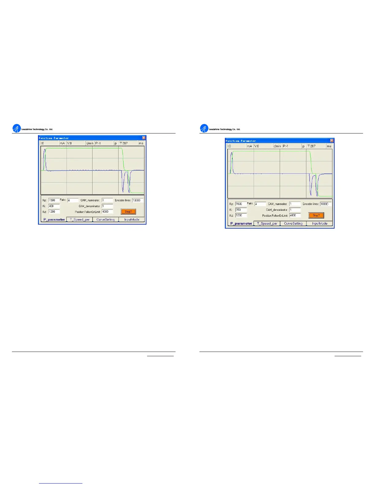
Figure 42: Position following error curve and velocity curve (Kp=1500, Ki=400 and Kd=1500)
Increasing Kp a little and reducing Ki to 350 can achieve a faster response with little
overshoot, namely get a response close to Critically Damped response. See Figure
43. Remember to download the parameter settings to the drive’s EEPROM when
you get a satisfying performance. You can also save them to a config file on the PC
harddisk then use these parameters for other drives. See detail in next chapter.
A
A
C
C
S
S
8
8
0
0
6
6
D
D
i
i
g
g
i
i
t
t
a
a
l
l
A
A
C
C
S
S
e
e
r
r
v
v
o
o
d
d
r
r
i
i
v
v
e
e
M
M
a
a
n
n
u
u
a
a
l
l
R
R
e
e
v
v
1
1
.
.
0
0
Tel: (86)755-26434369 41 Website: www.leadshine.com
Figure 43: Position following error curve and velocity curve (Kp=1500, Ki=350 and Kd=1200)
Tuning servo systems formed by ACS806 drives can be summarized as the
following rules.
1. If servo system is UNSTABLE, then the first thing of tuning is to stabilize the
system. You can increase Derivative Gain of Position Loop (Kd) or decrease
Proportional Gain (Kp) or Integral Gain of Position Loop (Ki).
2. If servo system is UNDER DAMPED, then increase Kd or decrease Kp or Ki.
3. If servo system is CRITICALLY DAMPED, then stop tuning and download the
parameter settings to the drive’s EEPROM.
4. If servo system is OVER DAMPED, then decrease Kd or increase Kp or Ki.