CS-D403 Closed Loop Stepper Drive User Manual
Page | 4
3. Connections and LED Indication
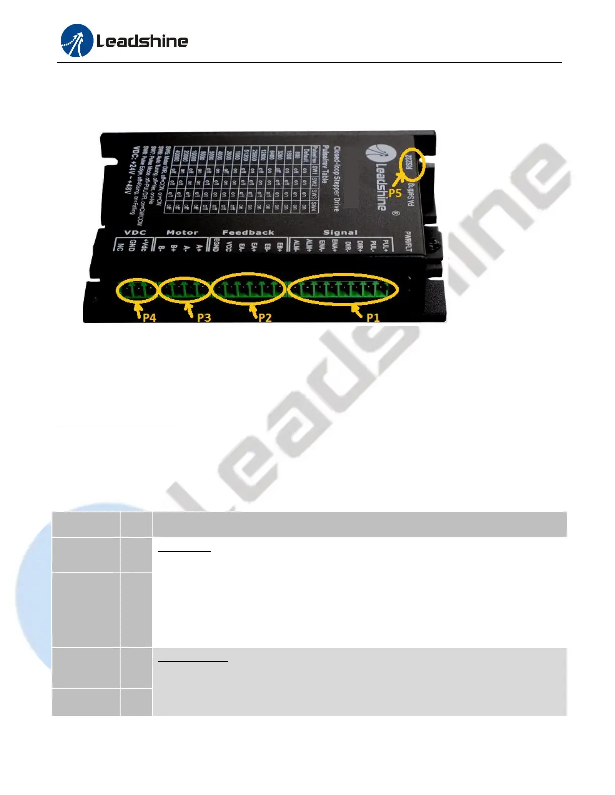
A CS-D403 closed loop stepper drive has 5 connection blocks from P1 to P5 (see figure 2).
Figure 2: CS-D403 connectors
3.1 Connector P1 – Control and Digital Output Connections
3.1.1 Pin Assignments of P1
The P1 connector in Figure 2 contains connections for control signals and a configurable digital output.
a) Pinout Definitions
There are 3 control signals for pulse, direction, and enable. See the following table for details.
Pulse signal: (1). In single pulse (pulse & direction) control mode, this input represents pulse
signal. A pulse signal is active at the rising or falling voltage edge (set by DIP switch SW8).
(2). In double-pulse (CW/CCW) control mode (set by DIP switch SW7), this signal input
represents clockwise (CW) pulse, and is active at both high voltage level and low voltage level.
(3). 4.5-5V for voltage HIGH, 0-0.5V for voltage LOW (same for DIR signals). (4). Pulse
width should be set to 2.5μs or longer.
Direction signal: (1). In single pulse (step & direction) control mode, this signal’s low and high
voltage levels represent the two directions of motor rotation (e.g. clockwise and
counterclockwise). (2). In double-pulse (CW & CCW) control mode, this signal represents
counterclockwise (CCW) rotation. It is active at both voltage high level and low level. (3).