A
A
A
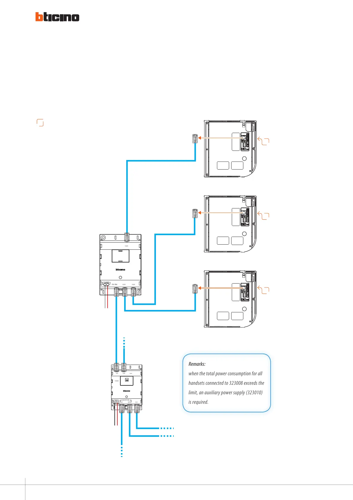
basic apartment interface connection
handset
handset
323002
323008
handset
1 2
POWER
– +
To IU 4
Sub System OUT
POWER
– +
Sub System IN
To IU 2
Remarks:
when the total power consumption for all
handsets connected to 323008 exceeds the
limit, an auxiliary power supply (323010)
is required.
Diagram 2
A
The indoor units must have the same address FFII#I#I.
98
WIRING DIAGRAMS - VARIANTS