F F I I #I #I
F F I I #I #I
1 2 0 4
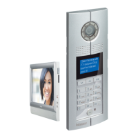
Handset configuration examples
Congurators position for handsets
321011
possiBle handseT
configuraTion procedure
Mode 1 Mode 2
Resistor conguration
(only for Colour)
√ √
Keyboard conguration √ √
RS232 conguration × ×
meaning of each
configuraTor socKeT pin
FF: Handset floor number.
II: handset household number.
#II: typical number of handsets
per floor.
poSition
Mode 1 Mode 2
F FF FF
F
I II II
I
#I
Default for #II is 04,
need not connect the congurator
II
(#II setup using same value for all system handsets)
#I
Example (A):
The number of handsets is 1204,
each floor has 4 handsets, the
system configuration Mode is
Mode 1, the handset configuration
should be as follows:
poSition configuration Value reMarkS
F 1
F 2
I 0 It is ok not to insert congurator 0
I 4
#I Because the default value of #II is 4, no congurator
is needed
#I
A
45
GUIDED45 SyStEm
WWW.LEGRAND.COM