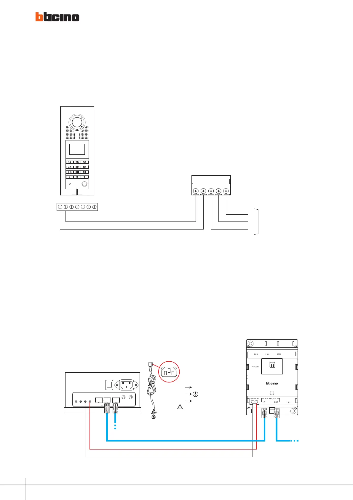
Diagram 6
wiring diagrams - door lock relay connection
S-
S+
C
NC
NO
L+ L
-
NO
NC
C
322010
322011
346250
N.B.: Cable size 1 mm
2
and max distance 2 meters
8A cosϕ = 1 24 Vac/24 Vdc
4A cosϕ = 0.7 24 Vac
3A cosϕ = 0.4 24 Vac
B DCA
+
– –
+
N L
L
E
N
- Blue N
-
Yellow and green
- Brown
L
AC input
This wire must be connected
to earth ground
B DCA
+
– –
+
N L
L
E
N
- Blue N
-
Yellow and green
- Brown
L
AC input
This wire must be connected
to earth ground
1 2
Riser OUT
Riser IN
323002
323005 / 323010
Diagram 7
addictional poower supply connection
102
WIRING DIAGRAMS - VARIANTS