B DCA
+
– –
+
N L
L
E
N
- Blue N
-
Yellow and green
- Brown
L
AC input
This wire must be connected
to earth ground
BACK BONE
L+ L- GND GNDUNLOCK +12VDAS L+ L- GNDUNLOCK +12VDAS
322011322010
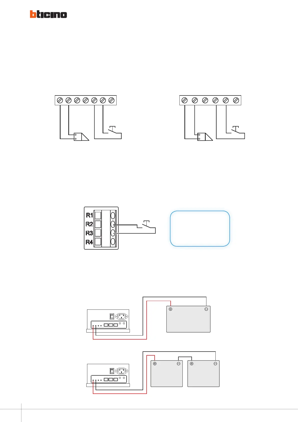
Diagram 10
323005 / 323010
323005 / 323010
B DCA
+
– –
+
24Vdc BATTERY
B DCA
+
– –
+
12Vdc BATTERY 12Vdc BATTERY
back-up battery connection
Diagram 12
floor call connection
Diagram 11
B DCA
+
– –
+
24Vdc BATTERY
B DCA
+
– –
+
12Vdc BATTERY 12Vdc BATTERY
Enable the service with the code:
#686868#16#1 “LONG TONE”.
INTERNAL UNIT
connection of entrance Hall pusHbutton to tHe entrance panel
104
WIRING DIAGRAMS - VARIANTS