152
322010
10
8
7
6
5
4
3
2
1
9
11
N N #F #F #I #I
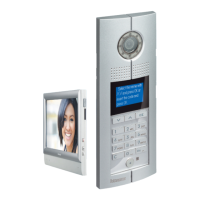
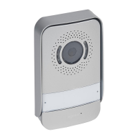
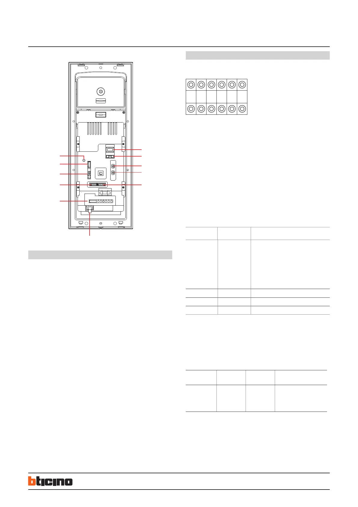
Digital colour entrance panel
Legend
1. NN #FF #II: configurators housing
2. ISP: entrance panel software upgrade connector
3. SPK: loudspeaker volume adjust
4. MIC: microphone volume adjust
5. VIDEO-IN/GND/NC/+12V/LED : entrance panel camera and compensation Lamp
connector
6. RJ45 SYSTEM BUS connector
7. 7 poles connector for :
– +12V/GND power supply for access control module (Optional)
– UNLOCK signal output from access control module (Optional)
– GND/DAS electronic lock status signal connector
– LOCK-/LOCK+ electrical door lock connection
8. SPK-OUT/GND/GND/SPK-OUT: entrance panel loudspeaker connections
9. DIP SWITCH for video gain setting - see specific section
10. ANT access control antenna module connection (Optional)
11. RESET - Password reset pushbutton
Configuration
When the biggest number of #FF in whole system is ≤ 20, and the biggest number
of #II is ≤4, and the total risers number is ≤ 50, we recommend to choose (MODE 1)
configuration for system.
When the biggest number of #FF in whole system is more than 20, or the biggest
number of #II is more than 4, we suggest to use (MODE 2) configuration to setup #FF
(choose the biggest number #FF of system) and #II (choose the biggest number #II of
system), then calculate total IU number of system. If the total number (#FF * #II * R ) is
less or equal 4000, use of (MODE 2) is suggested.
MODE 1 example
Entrance panel must be configured for following parameters:
NN : Entrance panel number
# FF : Floor quantity in a riser
# II : Maximum apartment quantity per
floor in a riser
Two different configuration modes available for whole system :
configuration MODE 1 and configuration MODE 2. The main characteristics for each
configuration mode are listed below.
#FF
FOR EACH RISER
#II
FOR EACH FLOOR
CAN SYSTEM CONFIGURATION MODE 1 BE
USED?
≤ 20 ≤4 YES,
but it is necessary to calculate the total num-
ber of handsets for whole system according to
Mode 1 conguration. If the total number cal-
culated is 4000 or less, Mode 1 conguration
is possible, if the total number is over 4000,
Mode 2 must be considered.
> 20 ≤ 4 NO
≤20 > 4 NO
> 20 > 4 NO
MODE 2 example
For example: if the highest building of a project has 25 floors, and the max. number
of apartment for floor is 8, with 15 risers in total. Then for mode 2, the #FF should be
25, while #II should be 8. Make the calculations according to following table to judge if
mode 2 configuration can be used.
#FF FOR EACH
RISER
#II FOR EACH
FLOOR
TOTAL RISER CAN SYSTEM CONFIGURA
TION MODE 2 BE USED?
25 8 15 25*8*15=3000
3000<4000
30 - 25*8*30=6000
6000>4000
Rear view
BT00466-b-EN 30/05/2013
 Loading...