323002
1 2
IU1
IU2
IU3
IU4
323002
1 2
IU1
IU2
IU3
IU4
323002
1 2
IU1
IU2
IU3
IU4
ON
SD
1
2
3
4
ON
SD
1
2
3
4
B DCA
+
– –
+
BUS
BUS
323005
322011
B DCA
+
– –
+
323005
L + +12L – UNLOCK
PBL1
322011
323003
IN
IN
IN
IN
OUT
OUT
S2S1C FG
C
F
1
C
F
2
C
F
3
C
F
4
C
F
5
C
F
6
C
F
7
M
PO WER
+
-
SY STE M
I N
OUT PUT1
OUT PUT2 O UTPU T3 OU TPUT4
OUT PUT5
SYSTEM
OUT
OUT PUT8 O UTPU T7 OU TPUT6
POWER L1 L2
IS P
C
F
1
C
F
2
C
F
3
C
F
4
C
F
5
C
F
6
C
F
7
M
323017
OUT
OUTPUT8
OUTPUT7
OUTPUT6
OUTPUT5
OUTPUT4
OUTPUT3
OUTPUT2
OUTPUT1
323002
1 2
IU1
IU2
IU3
IU4
323002
1 2
IU1
IU2
IU3
IU4
323002
1 2
IU1
IU2
IU3
IU4
IN
IN
IN
OUT
OUT
S2S1C FG
C
F
1
C
F
2
C
F
3
C
F
4
C
F
5
C
F
6
C
F
7
M
PO WER
+
-
SY STE M
I N
OUT PUT1
OUT PUT2 O UTPU T3 OU TPUT4
OUT PUT5
SYSTEM
OUT
OUT PUT8 O UTPU T7 OU TPUT6
POWER L1 L2
IS P
C
F
1
C
F
2
C
F
3
C
F
4
C
F
5
C
F
6
C
F
7
M
323017
OUT
OUTPUT8
OUTPUT7
OUTPUT6
OUTPUT5
OUTPUT4
OUTPUT3
OUTPUT2
OUTPUT1
323002
1 2
IU1
IU2
IU3
IU4
323002
1 2
IU1
IU2
IU3
IU4
323002
1 2
IU1
IU2
IU3
IU4
IN
IN
IN
IN
OUT
OUT
S2S1C FG
C
F
1
C
F
2
C
F
3
C
F
4
C
F
5
C
F
6
C
F
7
M
PO WER
+
-
SY STE M
I N
OUT PUT1
OUT PUT2 O UTPU T3 OU TPUT4
OUT PUT5
SYSTEM
OUT
OUT PUT8 O UTPU T7 OU TPUT6
POWER L1 L2
IS P
C
F
1
C
F
2
C
F
3
C
F
4
C
F
5
C
F
6
C
F
7
M
323017
OUT
OUTPUT8
OUTPUT7
OUTPUT6
OUTPUT5
OUTPUT4
OUTPUT3
OUTPUT2
OUTPUT1
CF1 CF2 CF3 CF4 CF5 CF6 CF7
0 40 2 7 1 1
M
1
CF1 CF2 CF3 CF4 CF5 CF6 CF7
0 40 9 6 0 1
M
1
323017
323017
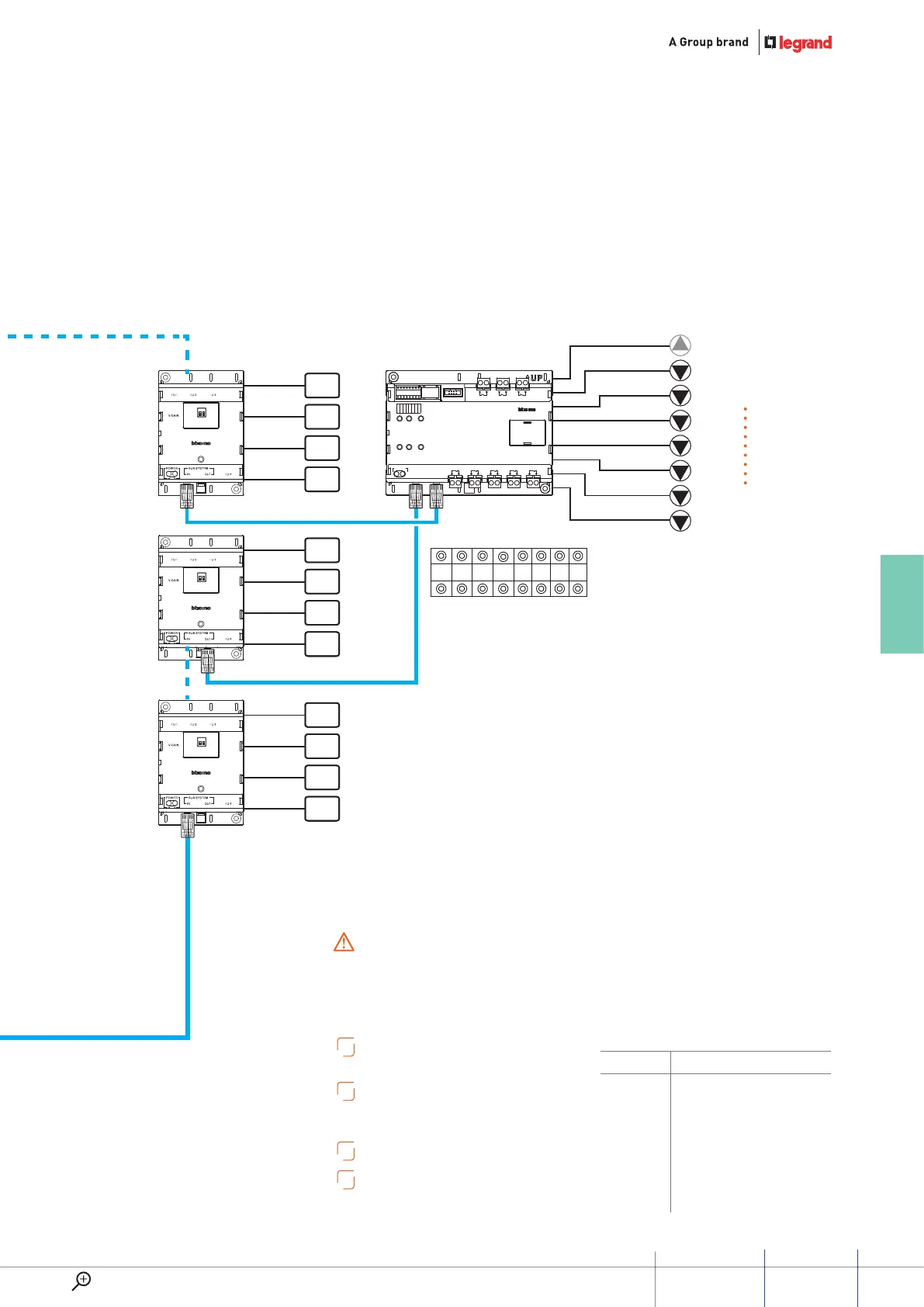
LIFT CTRL. 1
FLOOR 1 FLOOR 2
UP key of lift in 1 groud floor
Down key of lift in 8 floor
Down key of lift in 3 floor
Down key of lift in 2 floor
Down key of lift in 7 floor
A
To install alternative internal units, refer to
wiring variant section.
B
To install alternative Entrance panel, refer to
wiring variant section.
Device configuration by SF2 software.
C
Set internal IMPEDANCE SWITCH to ON.
D
Auxialiary PWS must be used in relation with the system
distance extension - see specific section.
Configure and insert the jumpers with the system
SWITCHED OFF. Also every time the configuration is
modified the pws must be switched OFF and ON again,
waiting about 1 minute.
WARNINGS:
ITEM DEscrIPTION
322011
Digital call entrance panel
323005 Main & Auxiliary power supply
303003 Riser shunt
323002 Floor shunt
323017 Lift control interface
L1 Electric door lock 12V - 4A impulsive
PB Door lock release pushbutton
87
GUIDED45 SyStEm
WWW.LEGRAND.COM