11
KEOR T
Operating Manual
2 Password protected menus for SETTINGS and COMMANDS;
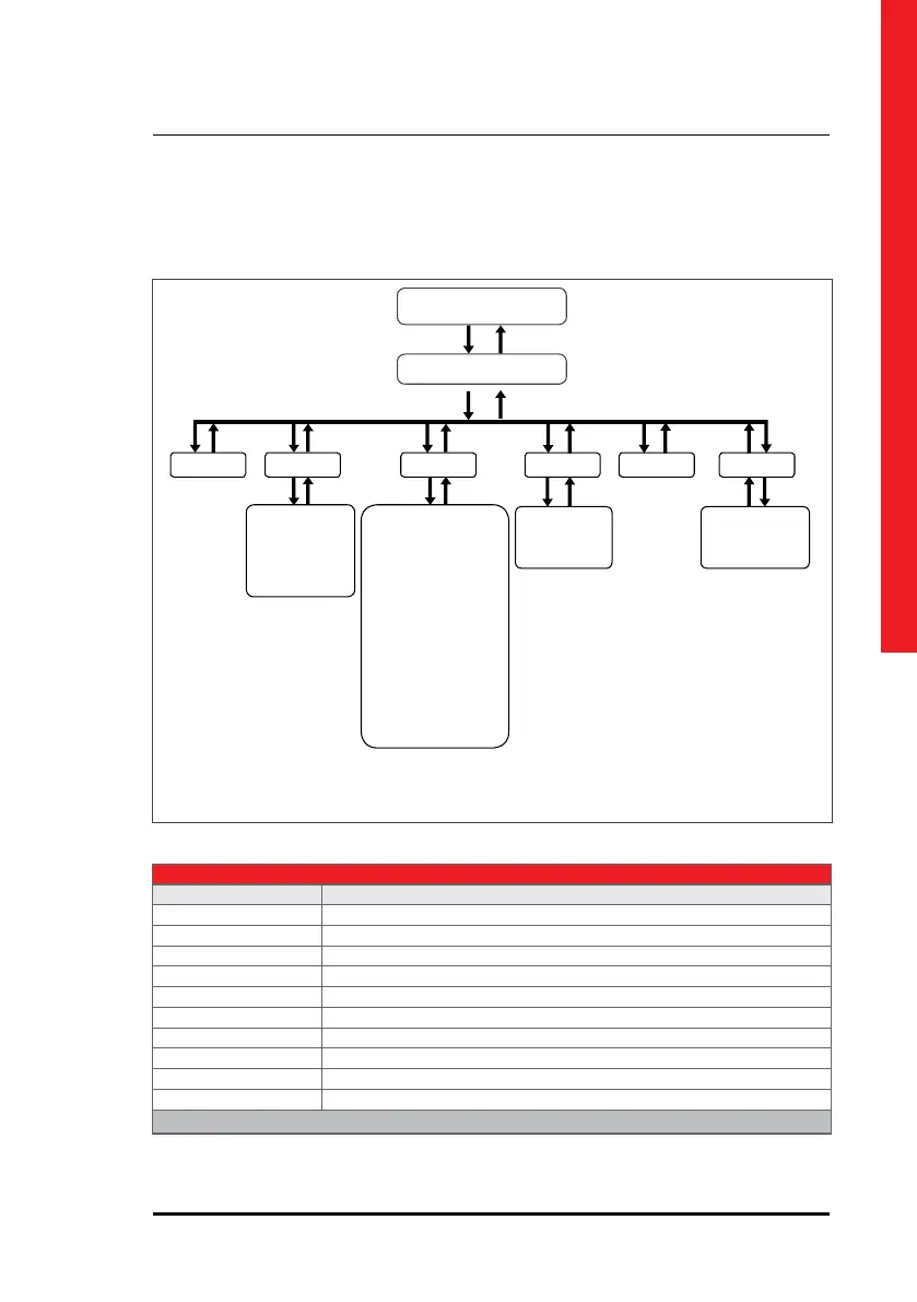
Figure.5-1
5.1. Front Panel Segments
Front panel consists of two segments: Colour Touch screen Graphical Control Panel and UPS Status LED
Bar oers detailed information about UPS.
The front panel is located at the top of the UPS which informs the user about operating status, alarm
conditions and measurements. It also provides access to control commands and user parameters settings.
Main screen image shows the energy ow path and Operation Modes. The information of the current
operation is written at the upper side of the panel. Additionally, the energy ow path is given by a graphical
animation.
5. Human Machine Interface
Energy Flow Diagrams
Menus
Alarms
Measurements Settings
Diagnostics
About
Commands
• Output Power
• Output
• Battery / DC
• Bypass
• Rectifier
• Diagnostics
• Events
• Details
• Piriortiy Mode
• Battery Test
• Authorizations
• Relay Funtions
• Options
• Communication options
• Event Logs
• Output Voltage
• Output Frequency
• Battery
• Parallel Mode
• Emergency Switching Device
• Maintenance Alarm
• Generator Mode
• Relay Functions
• Time
• Date
• Language
Password Authorizations
User Password by default: 1111 Service Password: access only to LEGRAND UPS Technical Service Personnel
• Options • Events Logs
• Display Brightness • Output Voltage
• Relay Functions • Output Frequency
• Time • Battery
• Date • Parallel Mode
• Language • ESD
• Priority Mode • Generator Mode
• Battery Test • Communication Options
• Maintenance Alarm
• Authorizations
Table.1

 Loading...