4
No: IS-0685 – Rev. 2
INSTALLATION OVERVIEW
INSTALLATION LOCATION RECOMMENDATIONS
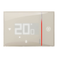
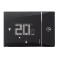
THERMOSTAT MOUNTING
1. 120 volts may cause serious injury from electrical shock. Disconnect electrical power to the HVAC system before
starting installation. This system is a low-voltage system.
2. Improper installation may cause serious injury from electrical shock. HVAC systems must be installed by a
qualied contractor in accordance with NEC Standards and applicable local and state codes.
3. Installation of Vantage products should be performed or supervised by a Certied Vantage Installer.
4. DISCONNECT POWER TO ALL HVAC EQUIPMENT AND/OR ZONE CONTROL PANELS
• If the thermostats are wired to a zone control panel, there is generally one set of input terminals supplying power
to the thermostats and dampers. This must be disconnected.
• If the thermostats are wired directly to HVAC equipment, the power must be shut off at the equipment. This
can generally be accomplished by turning off the disconnect switch located near the equipment. If an obvious
disconnect switch is unavailable, you will need to turn the circuit off using the fuse or circuit breaker. Remove the
fuse or shut down the circuit breaker serving the equipment.
5. Failure to disconnect power could result in damage to the HVAC equipment or thermostats. Leave power
disconnected until all other electrical connections have been made and checked for accuracy.
WARNING - CAUTION!
THERMOSTATS SHOULD BE MOUNTED:
• On an interior wall, in a frequently occupied space
• Approximately 5 feet above oor
• At least 18” from outside wall
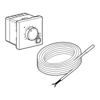
• Thermostat can be mounted to a vertical junction box.Direct
connection of outdoor or indoor sensors
• Allows for temporary override of Vantage System without
altering initial programming
• Automatic set points controlled through the Vantage System
• Backward compatible
DO NOT MOUNT THERMOSTAT:
• Behind doors, in corners or other dead air spaces
• In direct sunlight, near lighting xtures, or other appliances
that give off heat
• On an outside or unconditioned area wall
• In the ow of a supply register, in stairwells, or near outside
doors
• On a wall with concealed pipes or ductwork
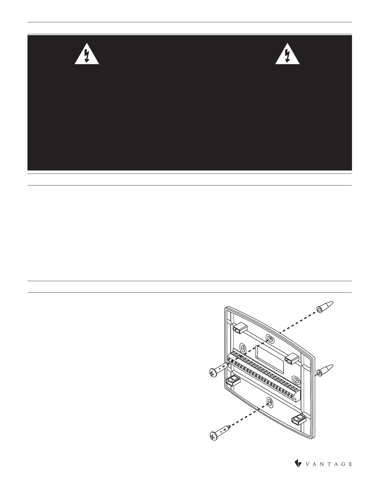
1. Remove the rear mounting plate from the thermostat.
2. Pull wires through the opening in the rear mounting plate.
3. Position and level the mounting plate of the thermostat on wall
and mark the hole locations with a pencil.*
4. Drill 1/4” holes and insert supplied anchors (drywall only).
5. Place mounting plate over anchors, insert and tighten screws.
*The mounting plate may be anchored to a single gang box.
TIP: The CC-WLINT/RLINT will t through the hole in the rear mounting
plate.
6. Seal wire entry holes to prevent drafts affecting temperature readings.