6
No: IS-0685 – Rev. 2
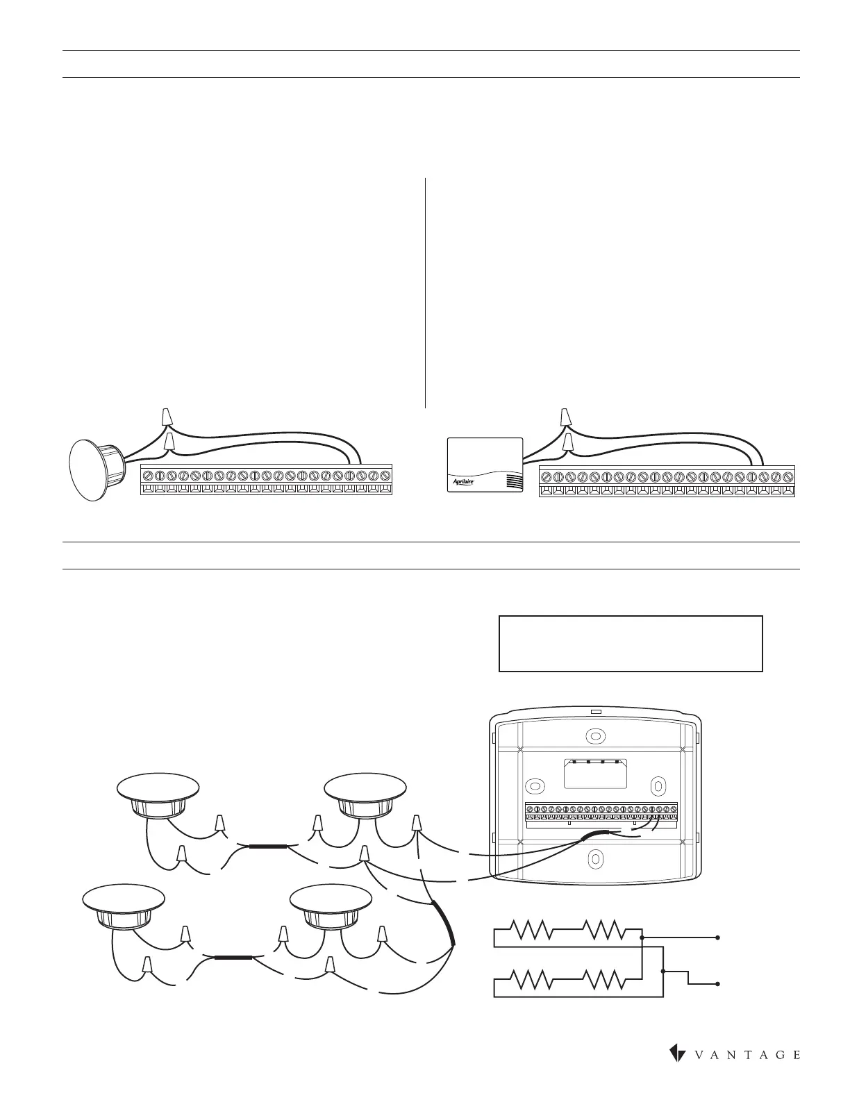
REMOTE TEMPERATURE SENSORS (OPTIONAL)
TEMPERATURE AVERAGING
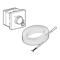
A remote indoor temperature sensor can be used if the thermostat is to be mounted in a concealed location. A Vantage ush mount
sensor, part number FLUSHSENSOR, or surface mount sensor, part number SENSOR-SMT, can be attached to the T1 and T2
terminals and mounted in a recommended area. The remote sensor must be enabled in the installer set-up menu, and once enabled
will override the thermostat’s internal temperature sensor. (See Installer Setup Menu in SECTION TWO – SETUP & TESTING). For
temperature averaging connect 4 or 9 indoor sensors as illustrated below.
Connect multiple thermostat sensors for temperature averaging. Only 4 or 9 sensor congurations are allowed for averaging. Only
wire multiple sensors as shown.
FOUR SENSOR TEMPERATUREAVERAGING – SCHEMATIC
4 Sensors(see additional information shipped with sensor)
NOTE: Wiring shown is using model FLUSHSENSOR.
Use the same wiring for model SENSOR-SMT.
Remote temperature sensor should be mounted:
• On an interior wall, in a frequently occupied space
• Approximately 5’ above the oor
• At least 18” from the outside wall
• Using less than 300’ of wire
Outdoor temperature sensor should be mounted:
• Behind doors, in corners or other dead air spaces
• In direct sunlight, near lighting xtures, or other appliances
that give off heat
• On an outside or unconditioned area wall
• In the ow of a supply register, in stairwells, or near outside
doors
• On a wall with concealed pipes or ductwork
• Near 120VAC lines
FLUSH MOUNT SENSOR
(Part # FLUSHSENSOR)
SURFACE MOUNT SENSOR
(Part # SENSOR-SMT)
B+ A+ B- A- C B O Y Y2 G RC RH W2 W R S2 S1 T1 T2 RSB RSA
B+ A+ B- A- C B O Y Y2 G RC RH W2 W R S2 S1 T1 T2 RSB RSA
2-WIRE THERMOSTAT CABLE
R=RED • W=WHITE
W
R
W
R
B+ A+ B- A- C B O Y Y2 G RC RH W2 W R S2 S1 T1 T2 RSB RSA
R
R
W
W
W
R
W
R
R
W
S1 S2
T1
T2
S3 S4
W
R