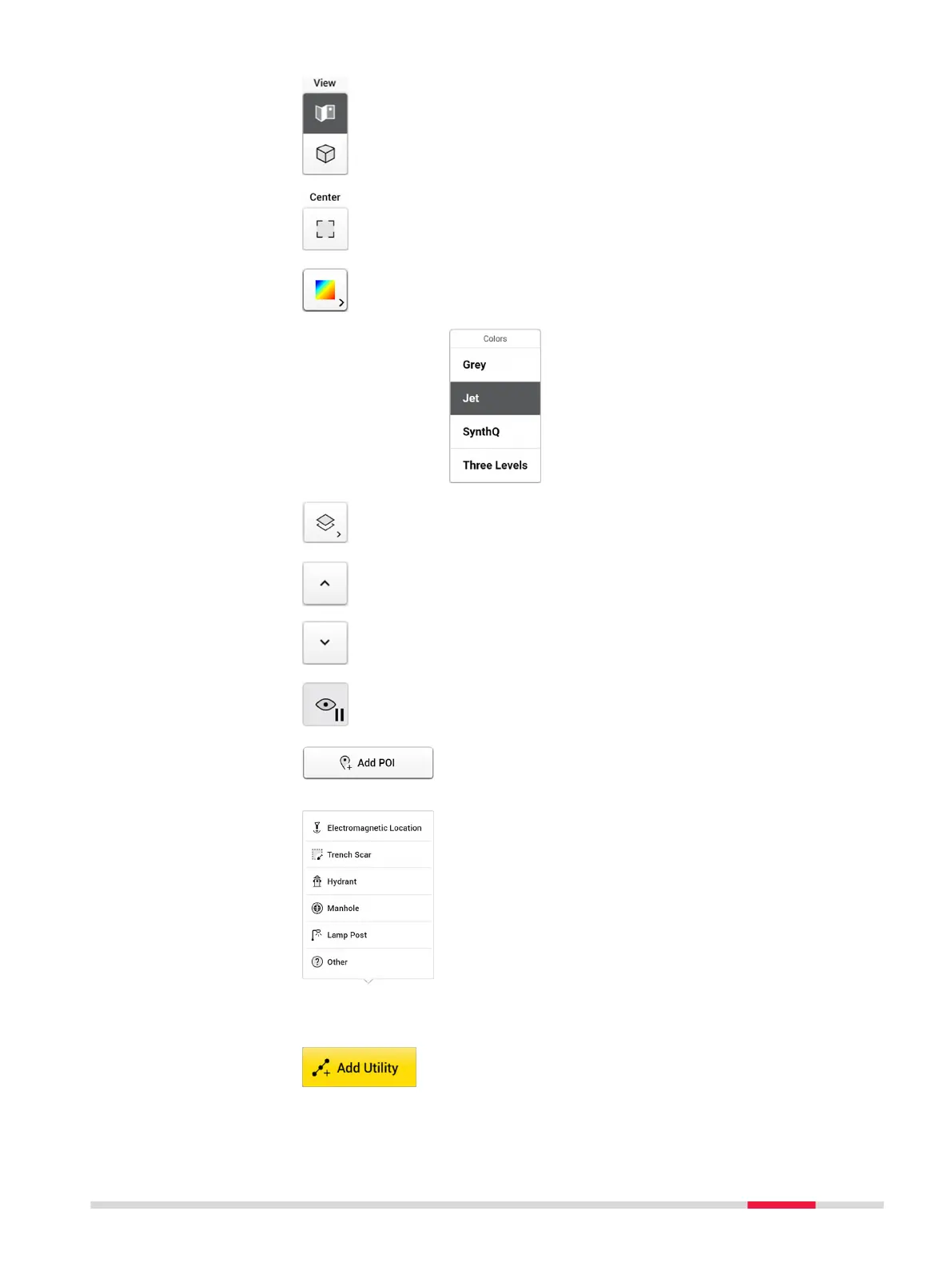
2D and 3D View button.
•
2D view is the top view from above and sees the
entire area in a at view.
•
3D view allows rotation to view utilities in various
depths.
Zoom to and centre on grid.
Toggle this button for displaying the tomography in dif-
ferent colour schemes. This function helps identifying
utilities in the tomography view.
Show/hide the layers and grid lines.
Change the depths.
☞
It is important to review the tomography of all
depth slices to nd utilities in the correct
depth.
Tap button Start/Stop Autoslicing to pause an auto-
matic animation to go through all depth slices and start
marking utilities.
Tap Add POI to add the points of interest if they were
not added during the acquisition. Following options are
available in the current POI list:
•
Electromagnetic Location is used to mark the
positions where the cable locator detects signals.
•
Trench Scar is used to mark where the road surface
has been opened and covered. This option gives
ideas where utilities may be buried.
•
Hydrant is used for giving additional information on
water pipes.
•
Manhole is used for giving additional information
on water, sewer or drainage.
•
Lamp Post is a great indication of power cables.
•
Lamp Post: Add own POIs which do not belong to
the listed types.
Tap Add Utility and start marking the utilities shown in
each slice of the tomography view using either the pen
or your nger.
DXplore Software 37