The control panel window offers the
options of 10, 15, or 20 non-over-
lapping tomography slices.
The depth range of the tomography
slices are automatically adjusted
accordingly on the depth slider bar.
☞
Tomography congurations for each project are saved separately.
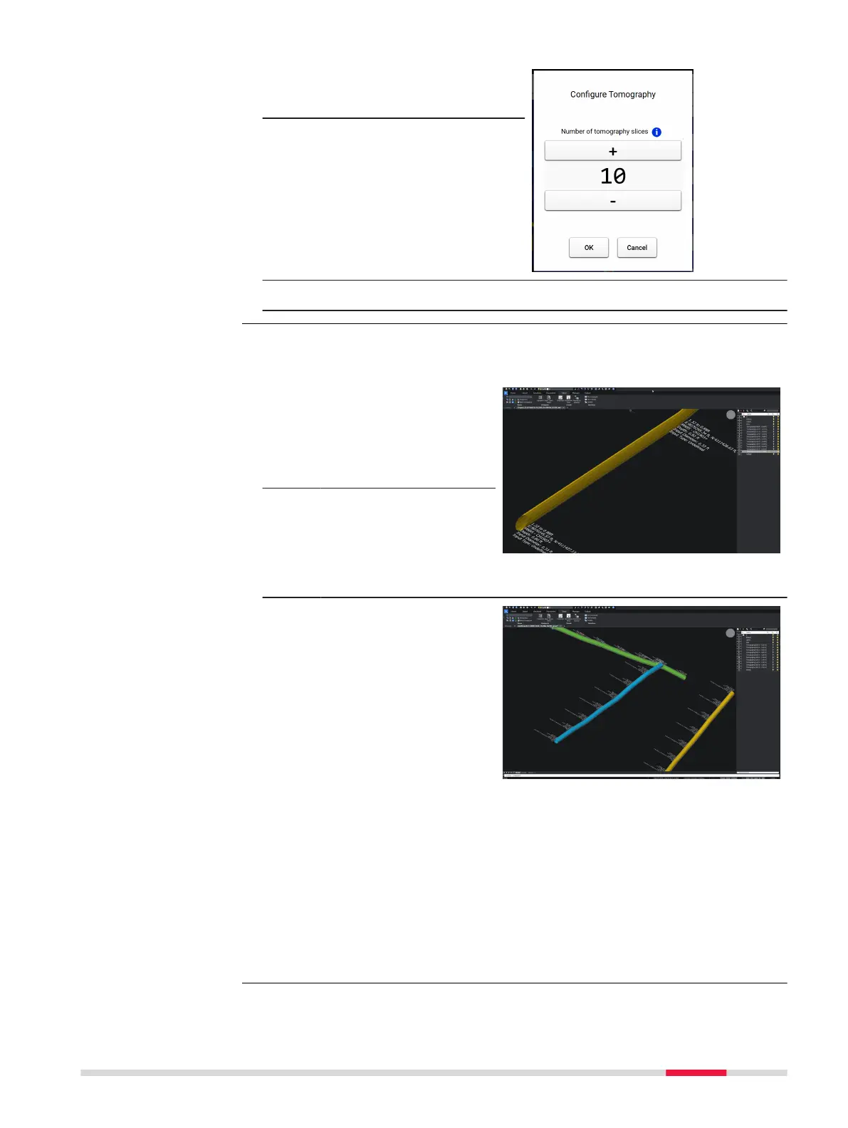
Exported DXF/DWG les permit viewing of utilities and anomalies in 3D view
while utility attributes are visualised (i.e. color, diameter).
1. Select the DXF/DWG
export option to export
additional PNG images
for all tomography
depth slices, along with
the CAD le.
2. A dedicated folder is
automatically created
on the designated des-
tination where both the
CAD le and the PNG
images will be stored.
☞
Layers such as utilities,
POIs, labels, tomo-
graphy slices can be
viewed or hidden once
exported and viewed in
a CAD viewer software.
For the AutoCad & Autodesk TruView software
☞
In the event that the software cannot automatically load the expor-
ted PNG images, it will be necessary to adjust the saved path of the
images through the CAD software settings.
This can be done by accessing the File references menu of the CAD
software and then change the path type of each PNG image to
Absolute.
The tomography images will be loaded and displayed in the CAD soft-
ware normally.
Enhanced DXF/DWG
le export
Step-by-step
DXplore Software 41