☞
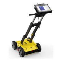
Adhering to the grid
size limits (minimum 4 x
4 m / 12 x 12 ft, max-
imum 11 x 11 m / 33 x
33 ft) at 50 cm / 1.5 ft
intervals and the estab-
lishment of full RTK
ensures that this step is
completed successfully.
7. To dene the grid size,
walk to the third point
and lock it as previ-
ously. A label is dis-
played in real time
indicating the corner
angle.
☞
The software utilizes a
rectangular-shaped grid
for the next stages.
Therefore, a 90-degree
angle should be dened
as correctly as possible
between the grid sides.
☞
The grid corner points
can be adjusted by
touching or clicking on
it and moving it to the
desired location. Then
relock it.
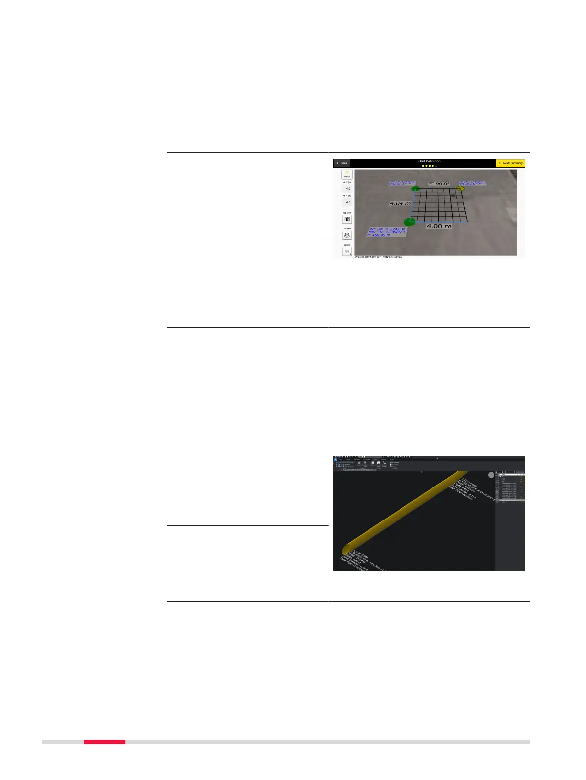
Exported DXF/DWG les permit viewing of utilities and anomalies in 3D view
while utility attributes are visualised (i.e. color, diameter).
1. Select the DXF/DWG
export option to export
additional PNG images
for all tomography
depth slices, along with
the CAD le.
2. A dedicated folder is
automatically created
on the designated des-
tination where both the
CAD le and the PNG
images will be stored.
Enhanced DXF/DWG
le export
Step-by-step
68 Procedures for Working with the DSX