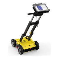
3. Select the coordinate
system and later
optionally a CAD layer
or proceed with WGS84
and Google Maps layer.
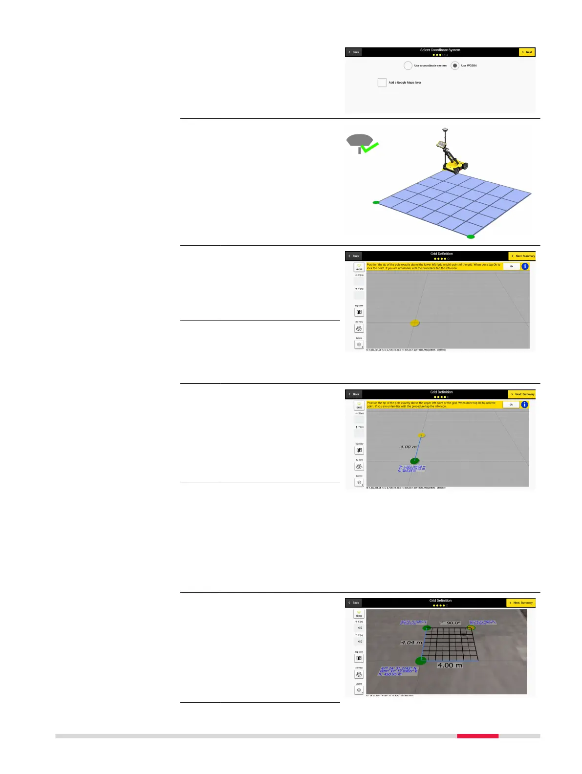
4. When a positioning
device is connected,
the new grid denition
screen provides grid
positioning and size
denition guidance.
5. Walk to the desired loc-
ation, place the pole tip
above the grid origin
and lock the point by
pressing the OK but-
ton.
☞
Make sure that RTK has
been fully established
beforehand. Otherwise
this step cannot be
completed successfully.
6. To dene the grid ori-
entation, walk to the
second point (upper left
corner of the grid) and
lock it as previously.
In real time, a label is
displayed to reect the
size of the grid side.
☞
Adhering to the grid
size limits (minimum 4 x
4 m / 12 x 12 ft, max-
imum 11 x 11 m / 33 x
33 ft) at 50 cm / 1.5 ft
intervals and the estab-
lishment of full RTK
ensures that this step is
completed successfully.
7. To dene the grid size,
walk to the third point
and lock it as previ-
ously. A label is dis-
played in real time
indicating the corner
angle.
Procedures for Working with the DSX 73