24
8. Operation
Note:
The focus, like the movement of the stages, is
also adjusted to the magnification setting. When
viewed through the observation tube, the speed
always appears the same when rotating the set-
ting wheel.
8.7 Objectives
The desired objectives are swiveled into place
manually.
All objectives have an iris diaphragm. With the
iris diaphragm, the NUM aperture can be adjust-
ed continuously. Five ratchets make it easy to
adjust to identical settings on both sides.
The M macro-objectives can be used for coaxial
incident light. To avoid reflex, ARM caps must
be used in conjunction with the built-in pole fil-
ters → page 27ff.
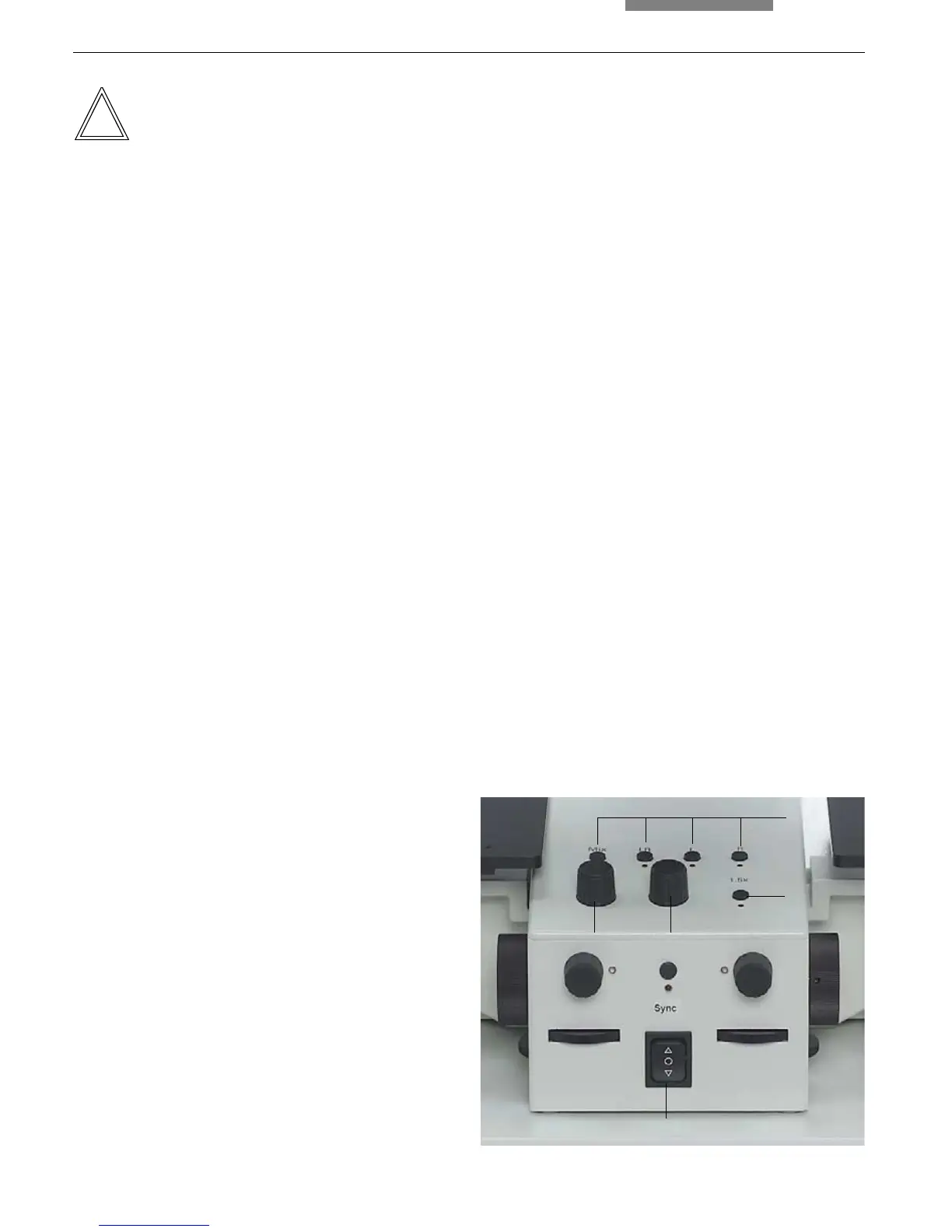
8.8 Magnification Changer
Use the button (21.3) to switch the magnification
changer on and off.
When the magnification changer is switched on,
the current magnification of both images is in-
creased by a factor of 1.5x. The LED underneath
the button (21.3) is illuminated.
The magnification changer controls the visual
and photo outputs simultaneously.
8.9 Diaphragm Setting
The motorized diaphragms allow transition from
a superimposed image to the separate view of
the right and left image, as well as the setting of
the dividing line.
Four diaphragm positions are already pre-
defined and can be selected by pressing the
corresponding button (21.4):
Mix The left and right images are super-
imposed (composite image method).
LR The left and right image appear side-
by-side. A line in the middle of the
field of vision separates the two im-
ages (split-image method).
L Only the left image is displayed.
R Only the right image is displayed.
The LEDs below the selector buttons (21.4) are
illuminated if one of the predefined settings has
been selected or set manually. Similarly, the
corresponding LED lights up if the dividing line is
moved.
The dividing line is moved to the left or to the
right by rotating the knob (21.2).
The knob (21.1) is used to change the width of
the dividing line.
4
3
21
Fig. 21 Control panel
1 Adjusting the width of the dividing line
2 Adjusting the dividing line in x direction
3 Magnification changer on/off
4 Predefined diaphragm settings
5 Adjusting the height of the stand
5