Do you have a question about the Leica SP8 and is the answer not in the manual?
Steps for powering on the microscope, scanner, lasers, and auxiliary components.
Instructions for turning on lasers and setting the pulse picker frequency in LASX.
Steps for selecting detectors (PMT/HyD) and acquisition modes in LASX.
Important checks before starting acquisition, like Autosave and HyD detector cooling.
System tuning for laser lines, detectors, gain, and emission spectra.
Adjusting format, speed, zoom, and pixel size for optimal image sampling.
Configuring Line, Frame, or Stack sequential scans in the acquisition mode.
Instructions for setting up Z-stacks using the joystick and 'Z position' knob.
Selecting Z-galvo or z-Wide, setting start/end points, and Z-step size.
Mandatory safety procedures, including warning lights, beam path, and protective coverings.
Guidelines for using laser safety goggles and avoiding reflective objects.
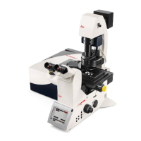
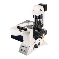
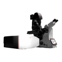
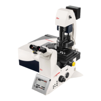
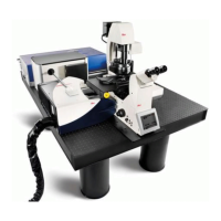
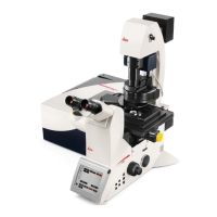
The Leica SP8 Upright Confocal Microscope, dated July 14, 2020, is a sophisticated imaging system designed for detailed microscopic analysis. It integrates various components to provide comprehensive imaging capabilities, including brightfield, fluorescence, and advanced confocal imaging.
The core function of the Leica SP8 is to capture high-resolution images of biological samples. It achieves this through a combination of an upright microscope, multiple detectors, and a versatile laser system. The microscope is equipped with a DMi6 upright microscope, capable of brightfield (BF) and fluorescence imaging in blue, green, and red channels. A BF TL Detector is included for transmitted light imaging, providing a basic overview of the sample.
For precise sample manipulation, the system features a scanning stage with z-Galvo and Navigator functionalities. This allows for the acquisition of overviews and the selection of specific regions of interest for detailed examination. The scanner also supports scan-field rotation, offering flexibility in image orientation.
The detection system is robust, comprising two PMT (photomultiplier tube) detectors for general signal acquisition. Additionally, it includes two Hybrid Detectors: one for normal operation, offering higher sensitivity and reduced noise compared to PMTs, and another Hybrid Detector SMD (Super-Resolution Microscopy Detector) optimized for fast imaging applications like FLIM (Fluorescence Lifetime Imaging Microscopy) and FALCON (FAst Lifetime CONtrast).
The laser system is a key component, providing multiple excitation wavelengths. It includes a 405 nm laser line and a White Light Laser (WLL) that can generate up to eight laser lines simultaneously within the 470-670 nm range. This broad spectrum allows for excitation of a wide variety of fluorophores. The system also incorporates advanced imaging techniques such as FALCON, which uses a Pulse Picker for the WLL to enable fast lifetime contrast imaging, and LIGHTNING, a deconvolution method for super-resolution and highly sensitive imaging. For direct analysis of lifetime data, a Phasor plot feature is available.
The microscope is equipped with several objectives to suit different imaging needs:
Operating the Leica SP8 involves a structured startup and imaging workflow. To begin, the heating unit should be turned on if necessary. The system powers up by activating the 'PC-microscope' button, followed by 'scanner power' and 'Laser power'. The 'Laser ignition key' must be turned to 'on' to enable laser shutters, which act as an interlock. A fluorescent lamp can be switched on for visual examination of the sample. A manual switch at the back of the microscope controls the TL/LED light, which may need to be toggled if transmitted light is not visible through the eyepiece.
For imaging, the LASX software is launched. Users select a configuration, such as "Machine.xlhw" or "machine with zgalvo and DM6microscope." It is crucial to avoid using "Use last system settings" to ensure proper system initialization. Within LASX, users navigate to the 'configuration' - 'lasers' section to turn on desired lasers. The White Light Laser (WLL) power is typically set to 85% and its frequency to 80 MHz, which are usually the default settings. The pulse picker should also be set to 80 MHz to ensure optimal laser power.
Visual examination of the sample is facilitated by the microscope touchpad. The illumination menu allows selection of transmitted light (BF/TL) or fluorescent (FLUO) illumination. For transmitted light, the TL shutter is operated via the touchscreen, and intensity buttons on the left side of the microscope adjust LED intensity. For fluorescence, filter cubes (DAPI, GFP, RHO) are chosen from the front panel, and the IL-shutter is opened to view fluorescence. Intensity buttons also control the LED intensity for fluorescent illumination.
Focusing on the sample requires caution to prevent objective crashes. Users are instructed to raise the sample close to the objective while looking from the side, then observe through the eyepiece and always move the stage downward until the sample comes into focus. Visual illumination is automatically disabled during scanning, with the system switching to "CS" mode. For the TL detector, a manual lever at the back of the microscope may need to be switched back.
Data organization is managed within the 'User Config' section of LASX. Data can be saved in either a Folder or Project based structure. While TIFF files are saved in the folder-based structure, projects are saved as Lif/Lof files. A software bug advises against using folder-based file saving.
Acquiring confocal images involves selecting PMT detectors. Choosing FLIM automatically activates FLIM mode. All channels should be set to PMT initially, as the system automatically selects PMT or HyD. If the signal is good, users are advised to manually change HyD to PMT. Before starting, the Autosave option must be switched off in Open Project. A critical safety check involves ensuring the HyD SMD 1 detector cooling control lamp is green; if it is red, the system should not be used, and the BIF team must be contacted immediately.
Lasers are turned on from the configurations, and the acquisition mode is typically 'xyz'. A dye assistant helps plan confocal imaging by allowing users to enter fluorophores, choose PMT, and select imaging methods (simultaneous or sequential scanning) based on crosstalk and imaging speed. The pulse picker setting (80 MHz) is crucial for maintaining laser power.
The system automatically activates laser lines tuned to the excitation maxima of selected dyes, activates detectors with appropriate bandwidth, sets gain, and displays emission spectra. T-PMT can be switched on for transmitted light imaging, remembering to engage the Lever. Pressing "Live" provides an image preview. Laser power, detector bandwidths, and detector gain can be adjusted. Overexposure must be avoided by checking pseudo color or histogram, as it can damage detectors.
Setting up the confocal image involves adjusting parameters like gain, offset, scan field rotation, pinhole, zoom, and z-position, which can be done via software (Fig.4) or control knobs. Changing scan speed affects minimum zoom; up to 600 Hz, the minimum zoom is 0.75. The image format is adjusted using the Nyquist (optimal) button for proper sampling. Pinhole adjustments alter confocal section thickness, with the reference wavelength set to 580 nm (changeable). The default Signal-to-Noise Ratio (SNR) is AU 1. Applying frame or line averaging reduces imaging speed, and pixel dwell time should be checked.
Gated detection is a useful feature for removing reflection or background autofluorescence, but it is only possible with HyD detectors. This reduces autofluorescence or reflection with shorter lifetimes than actual fluorescence. Users activate gating, choose the detection window "in ns" for their fluorophore, and adjust during live scan.
Setting up sequential scans involves selecting the 'SEQ' symbol in the 'acquisition mode' menu. Users can choose between Line, Frame, or Stack sequential modes and set up the first configuration. In line sequential mode, PMTs and lasers are switched on/off between lines, but laser shutters and detector bandwidth remain constant, meaning no hardware movement occurs. This allows for reduced crosstalk and increased imaging speed. Configurations can be duplicated and unnecessary lasers deactivated. Sequential files can be saved and loaded.
Setting up a Z-stack involves using the 'Z position' knob on the control panel to select the first slice, as the joystick is always set to z-wide. Press 'begin' in the Z-stack menu, move focus up with 'Z position' to select the most superficial slice, and press 'End'. Z-step size can be set manually or optimized for Nyquist settings based on objective and pinhole.
Setting up time series (xyt or xyzt acquisition mode) involves activating 'minimize' in the 't' menu to estimate the minimal interval, or setting a custom time-lapse interval. Experiment duration or number of frames are selected, and 'Apply' is pressed. 'Start' initiates the time series. For tile scans, the Navigator module manual is referenced. A known bug exists where multi-positions with time-lapses and z-stacks in the Navigator may not update time interval and estimated times versus acquisition time. A workaround involves going to Lightning mode, deactivating the "lightning grade" link, and then setting up the experiment as a normal confocal.
Saving data is done by going to "Open projects" and saving directly to DATAINT (E). Data should be saved in the correct group folder, as data upload to scratch bioimaging is triggered by log off/log on.
Acquiring confocal images using the Lightning – Deconvolution environment involves selecting 'Lightning' from the drop-down menu. The Lightning slider controls deconvolution strength by adjusting pixel size, scan speed, number of averages, and pinhole settings. Users select an adaptive or global deconvolution strategy. Adaptive treats background and bright pixels differently, which may lead to non-linearity in quantitative measurements. Global treats every pixel uniformly. The embedding medium used for sample preparation is entered. Factory deconvolution settings can be changed in the 'Configuration, Lightning Tab'. Recommended settings are pinhole 0.6 AU and oversampling of 1.7. New settings can be saved and loaded. Deconvolution starts immediately online when the experiment begins, saving raw and deconvolved images as separate files.
Deconvolution processing after imaging in standard mode allows images taken in the regular confocal environment to be deconvolved afterwards. This involves selecting the image in Open project, going to the Process menu → Lightning, inputting parameters, and pressing "Apply".
Switching off the system requires switching off lasers in the LASX software ('Configuration'-'lasers') first, as simply closing the software does not turn them off. Files should be removed from the project list to prevent accidental data overwriting or deletion by other users. Data upload is triggered by log off/log on. After shutting down LAS AF and the computer, the 'Laser emission' key is turned to 'off', followed by switching off 'Laser Power', 'Scanner Power', 'PC/Microscope', and the fluorescent lamp.
The manual emphasizes several safety and operational guidelines that can be considered maintenance-related in terms of ensuring the longevity and proper functioning of the device.
Preventing crashes: The detailed instructions for focusing on the sample by looking from the side and moving the stage downward are crucial to prevent the objective from crashing into the sample or stage, which could cause significant damage to both the objective and the sample.
Detector cooling: The critical instruction to check if the HyD SMD 1 detector cooling control lamp is green, and to contact the BIF team if it is red, highlights the importance of maintaining optimal operating temperatures for sensitive detectors. This prevents overheating and potential damage to these components.
Avoiding overexposure: The warning to check for overexposure using pseudo color or histogram and the explicit statement that "Overexposing the detectors damage them" is a direct maintenance instruction. It guides users to operate within safe signal limits to protect the detectors from irreversible damage.
Software settings for data integrity: The advice to avoid "Use last system settings" and to switch off the Autosave option in Open Project before starting an acquisition are software-based maintenance practices. These prevent unintended configurations or data loss/corruption, ensuring that the system operates predictably and data is saved reliably. The instruction to remove files from the project list after use also helps maintain a clean and organized system for subsequent users, preventing accidental data overwrites.
Laser safety and system shutdown: The detailed shutdown procedure, including turning off lasers in the software, then the physical 'Laser emission' key, and finally the 'Laser Power', 'Scanner Power', 'PC/Microscope', and fluorescent lamp, is a critical maintenance routine. It ensures that all components are powered down safely and correctly, preventing electrical or laser-related hazards and prolonging the lifespan of the equipment.
General operational guidelines: The emphasis on proper configuration selection, careful adjustment of imaging parameters, and understanding the implications of different acquisition modes (e.g., line sequential vs. frame sequential) contributes to the overall "health" of the system by ensuring it is used within its intended operational parameters.
| Type | Confocal Microscope |
|---|---|
| Software | LAS X |
| Scanning Speed | Up to 428 frames per second |
| Dimensions | Varies depending on configuration |
| Weight | Varies depending on configuration |
| Imaging Modes | Confocal |
| Laser Lines | 405 nm, 488 nm, 514 nm, 561 nm, 594 nm, 633 nm |
| Laser Type | Diode, Argon, DPSS |
| Scanning Method | Galvanometric |
| Detectors | Hybrid Detectors |
| Spectral Detection Range | 400 nm - 800 nm |
| Objectives | 10x, 63x oil immersion |