4
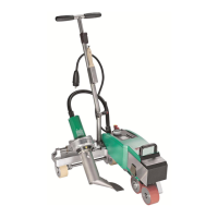
OPERATION LEISTER Uniplan E
Operational condition
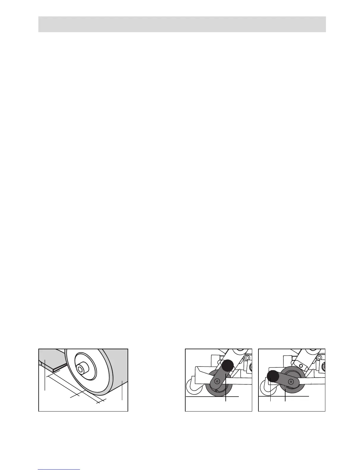
• Check the nozzle’s basic setting. (Detail A)
• Automatic drive
Automatic drive is adjusted as required, depending on nozzle position by means
of switch pin (26) and set screw (27).
• Guide roller
According to the application, the guide roller (25) is set to "active" (operational) or
"deactive" (non-operational) by means of guide roller knob (24) and guide roller
lever (23) (see Details B and C). The guide roller (25) causes the automatic welding
machine to carry out a straight run to the edge of the welding seam.
• Connect tool to the mains. Mains voltage must correspond with the voltage
rating stated on the tool.
• Switch on tool using main switch (17). Hot air blower (3) starts automatically.
• Important: undervoltage
In case the maximum temperature is not reached, reduce air volume by means of
manuel air vane (14) and potentiometer for air flow (20).
Tool positioning
• Swivel hot air blower (3) using swivel lever (22) up to the stop.
• Operate lifting device (11) by means of lifting device lever (16) so that
drive/pressure roller (6) and drive roller (9) are at no-load.
• If welding is being carried out by means of guide roller (25), lock guide roller lever
(23) into support bracket (12) (see Detail B).
• Position automatic welding machine into the overlap of the material to be welded.
The outside edge of drive/pressure roller (6) and guide roller (25) must line up with
the overlap edge of the material to be welded.
• Activate lifting device (11) by means of lifting device lever (16) so that the auto-
matic welder is ready to start.
Detail A Detail B Detail C
1–2 mm
40 – 50mm
6
4
24 2523
Guide roller
operational
Guide roller
non-opera-
tional