16
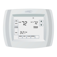
Drill Holes
Insert in hole until flush with wall.
WARNING
DO NOT over-tighten mounting screws. Doing so my distort the subbase
plastic housing and cause connection issues when installed the HD display.
10. Secure subbase with provided #6 x 1.25” pan-head screws (4).
11. Connect thermostat wiring to subbase screw terminals.
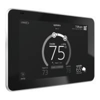
Mounting Display to Subbase
Install HD Display with UP arrow pointing
up when attaching to subbase.
1. Hold the HD Display by the edges, line it up with the subbase (horizontal
position), and move the HD Display toward the subbase.
2. Center the cavity on the back of the display over the subbase.
3. Gently press on the edges of the HD Display until you hear the mounting
snaps engage. Be careful not to apply force directly on the glass.
NOTE: Once the HD Display is connected, it may take up to 45 seconds for it
to power up.
4. To remove the HD Display from the subbase, grasp the left and right edges
of the HD Display and gently pull towards yourself.
NOTE: If the HD Display is removed from the subbase base, the HD Display
will shut down and will not be able to communicate with the system.
System can be controlled from mobile devices or consumer/dealer
web portals once registration has been completed.
5. Do not remove the label covering the HD Display screen until after power
is applied to the system.
Lennox Communicating Air Handler Electric Heat
Conguration
Auto Detection
During the system initial commissioning, the electric heat strips are auto-
detected and congured for the system. If electric heat is added after the
system had already been congured, then go to menu > settings > advanced
settings > view dealer control center > equipment > reset > re-congure
system to auto-detect the new electric strips.
Manual Conguration
OUTDOOR
AIR SENSOR
HEAT
1234
COOL
1234
DELAY
12 34
ADJUST
NORM + −
HUMIDIFICATION
SMART AUTO
EVENHEAT
1234
BLOWER
ONLY CFM
100
11 5
130
85
Y1−Y2
2−STAGE
COMPR
R−O
HEAT
PUMP
R−DS
DEHUM
OR
C
W1
W2
G
Y2
Y1
C
R
DH
H
L
O
DS
W3
FUSE3 AMP
XFMR 24V
24 VAC
COM
3
6
9
1
4
7
XFMR LINE
G
2
5
8
P8
L1
L2
L2 L1
INDOOR
BLOWER
POWER
EARTH
INDOOR BLOWER
SIGNAL
45 6
12 3
A92
INTEGRATED
CONTROL
OUTDOOR UNIT
LINK
I +
I −
I +I −RC
I +I −RC
THERMOSTAT
HUMIDITROL
DH
DISCHARGE
AIR SENSOR
HARMONY
PUSHBUTTON LED
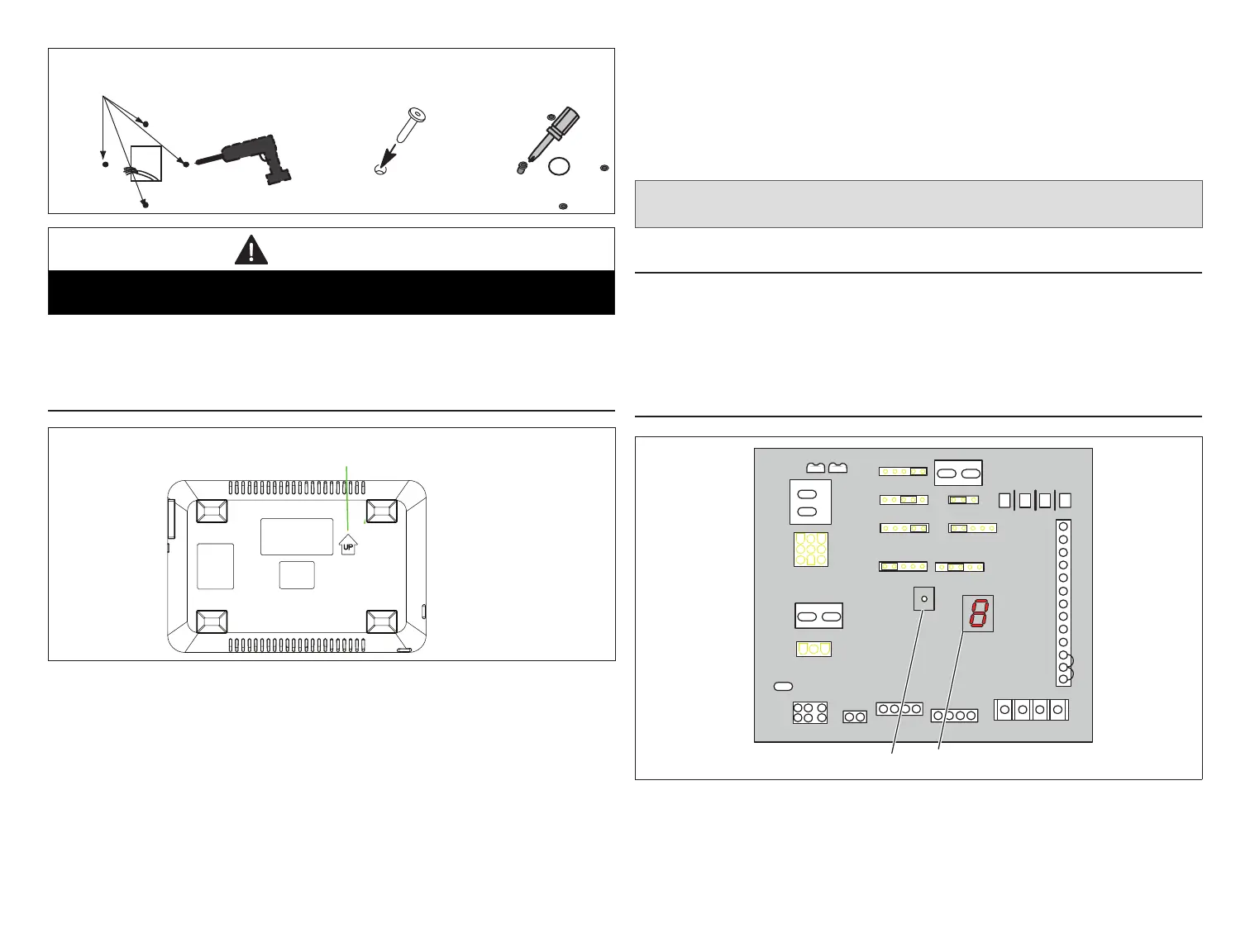
Figure 15. Air Handler Control
This procedure is applicable only to the CBX32MV-XX-230-6-06 and higher,
CBA38MV and all CBX40UHV models. Use this procedure if for some reason
the system is unable to auto-detect the electric heat strips:
• Power must be applied to the air handler but NOT to the smart hub.
 Loading...