9
DATS
(Required)
OATS (Optional)
IN-ZONE
THERMOSTAT S
PWR
D+
D-
C
PWR
D+
D-
C
PWR
D+
D-
C
See iHarmony Installation instruction for damper connection information.
INDOOR
DOOR” ON DAMPER CONTROL MODULE TO
CONNECT TO THE INDOOR UNIT.
PWR
D+
D-
C
iComfort Indoor
Unit
TS
IHARMONY ZONING
SYSTEM
To Smart
Hub
To indoor unit
To iHarmony
If unable to connect two wires
to indoor unit terminals then
pigtail wiring as exampled
here.
COMM
+
BUS
A B
S30 Smart Hub
HD
Display
Subbase
DATS
UP TO THREE
IN-ZONE
THERMOSTATS
ARE SUPPORTED
ACC1
ACC2
iComfort
Outdoor
Unit
If TSTAT terminal is present,
DO NOT use
.
-
+
A B
-
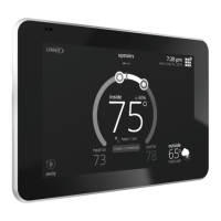
Figure 8. iComfort S30, Lennox Communicating Indoor and Outdoor Units, iHarmony Zoning System (Damper Control Module) and Zone Sensors
 Loading...
